UMSITRPDS3-1 On-Line Operation
November 2005
6-33
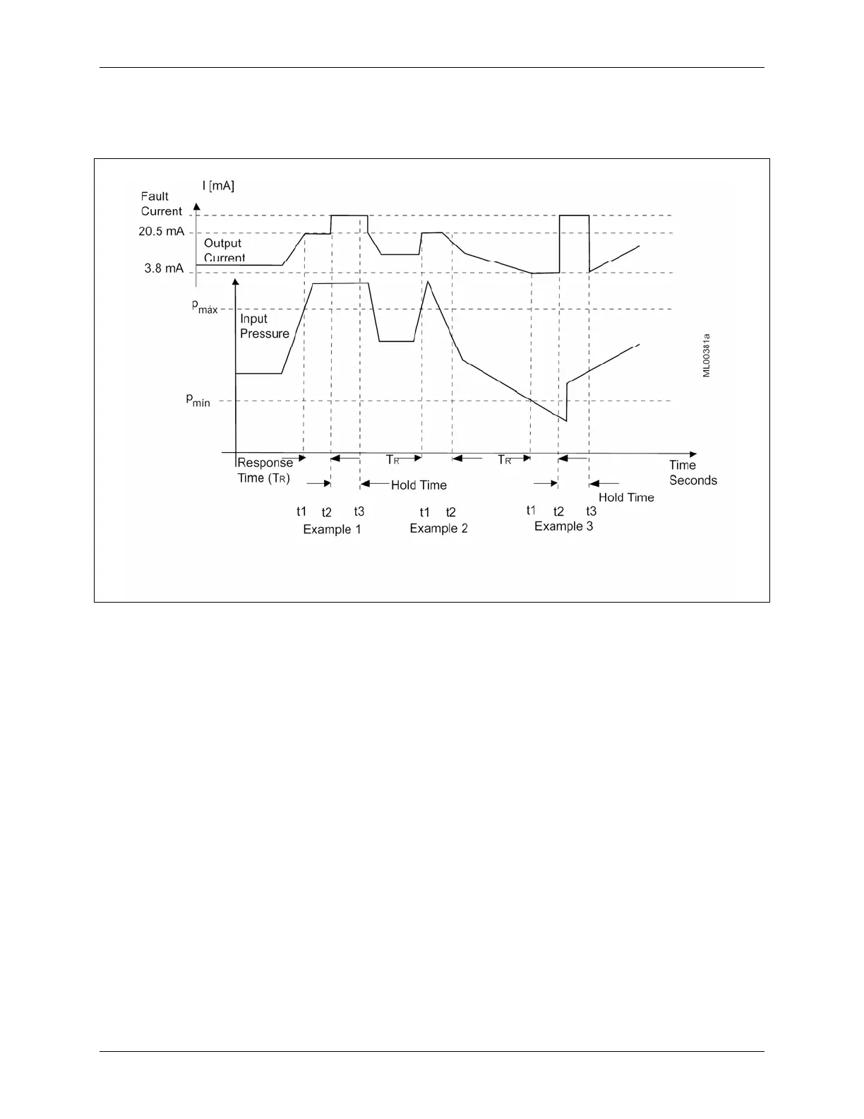
In the third example, the input spikes below minimum pressure. At t2 the response time expires and the
hold time begins. The transmitter outputs the fault current at t2 and holds that output until the hold time
expires at t3.
FIGURE 6-6 Saturation Monitoring Examples
6.4.20 Simulation
In the simulation mode, pressure and temperature values can be simulated within the transmitter without
the need for an external input signal. Transmitter circuitry can be exercised and the resulting values
output to an I/O module, controller, or other device to test the loop.
Simulation values are entered at the HART Communicator keyboard as described below. A pressure
simulation can employ either a “fixed value” or a “fixed ramp,” with the number of steps configurable.
Simulation data is stored in RAM only. Consequently, when a simulation is ended, simulation values are
deleted. Note that changing the temperatures by simulation has no effect on the measured pressure value.
Also, as long as the simulation is active, the transmitter will not react to changes in process pressure.
Figure 6-7 is a block diagram of a transmitter showing the measuring and simulation blocks.
Simulation (Pressure and Temperature)
1. In the Online menu, press 3 Device Setup.
2. In the Device Setup menu, press 2 Diagnostics/Service.
3. In the Diagnostics/Service menu, press 2 Simulation Test.
 Loading...


