UMSITRPDS3-1 Installation
November 2005
4-11
+
_
- +
4-20 mA
+
_
- +
4-20 mA
MG00349a
Controller,
Recorder,
Indicator, or
other 1-5 Vdc
Device
See Note 1
+
I
O
Transmitter
Terminals
See Note 5
250
See Note 2
System Power
Supply
_
+
Network
Junction
See Note 3
See Note 6
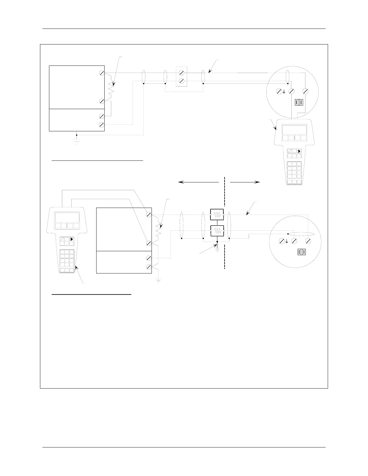
Network for Non-Hazardous Locations
_
Network for Hazardous Locations
Hazardous
Location
Non-Hazardous
Location
Controller,
Recorder,
Indicator, or
other 1-5 Vdc
Device
See Note 1
+
_
I
O
Transmitter
Terminals
See Note 5
250
See Note 2
System Power
Supply
+
_
See Note 3
See Note 6
See Note 4
The system power supply is shown separate from the host input device. In practice, it may be part of the host input
device. This device can be a HART or non-HART signaling device, a Primary Master, or a Secondary Master.
Network resistance equals the sum of the barrier resistances and the current sense resistor. Minimum value is 250
Ohms; maximum value is 1100 Ohms.
Connect the HART Communicator as shown in Figure 2-2 for hazardous and non-hazardous locations. The HART
Communicator is a non-polar device.
Supply and return barriers are shown. Interconnect all cable shields and ground only at the barriers.
For access to transmitter field terminals, remove the enclosure cap.
Maximum loop cable length is as calculated using the formula in Section 4.3.6.
FIGURE 4-6 Point-To-Point Network (Analog Mode)
 Loading...


