Appendix A - Online Configuration Map UMSITRPDS3-1
11-2 November 2005
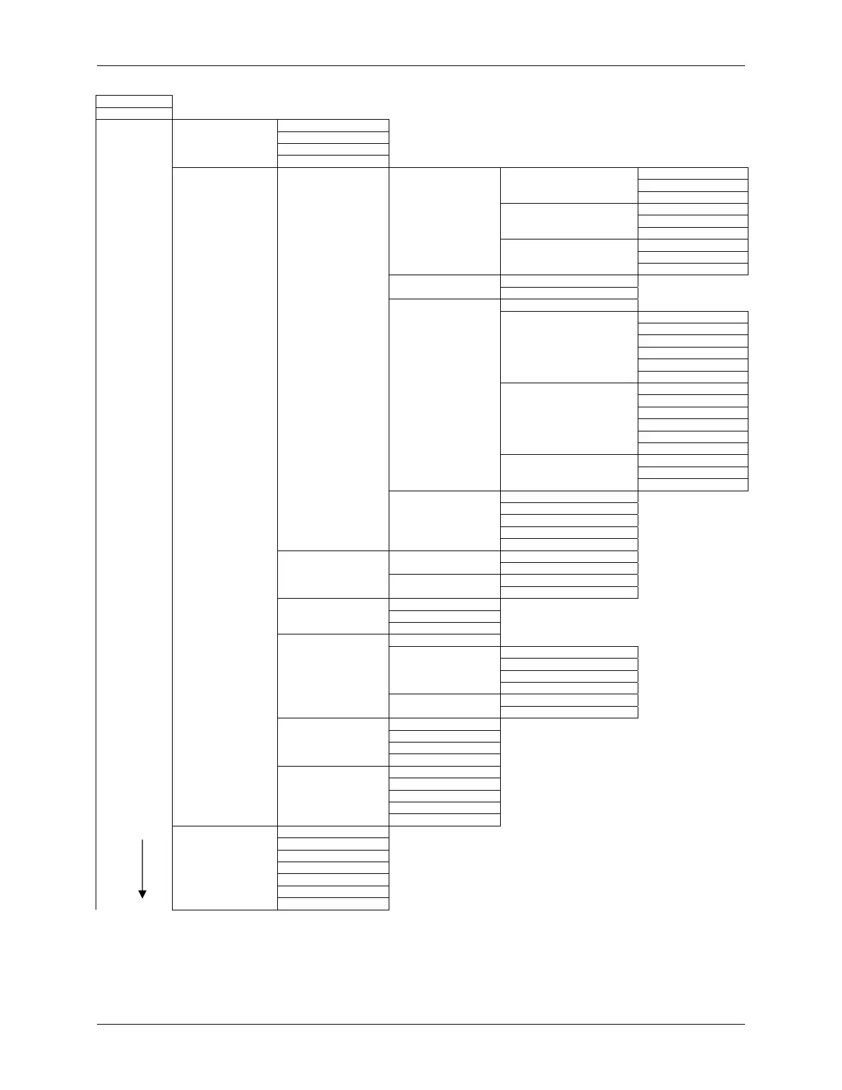
1 Pressure +
2 Type +
3 Device setup 1 Process variables 1 Pressure +
2 % range +
3 Analog output +
4 Sensor temperature +
2 Diagnostics/service 1 Diagnosis 1 Min/max pointer 1 Pressure pointer 1 Pressure maximum
2 Pressure minimum
3 Reset pointer
2 El Temperature pointer 1 E1 Temperature max
2 E1 Temperature min
3 Reset pointer
3 Sensor Temperature pointer 1 Sensor Temperature max
2 Sensor Temperature min
3 Reset pointer
2 Operating hours 1 Operating hours E1
2 Operating hours S
3 Warnings/alarms 1 W/A time unit
2 Calibrate interval 1 Calibrate status
2 W/A acknowledge
3 Calibration timer >
4 Calibration warning
5 Calibration alarm
6 W/A activation
3 Service interval 1 Service status
2 W/A acknowledge
3 Service timer
4 Service warning
5 Service alarm
6 W/A activation
4 AO saturation 1 Saturation alarm
2 Alarm duration
3 Alarm activation
4 Status 1 Status summary
2 Hardware/Firmware status
3 Diagnostic alarm status
4 Diagnostic warning status
5 Simulation status
2 Simulation/Test 1 Simulation 1 Loop Test
2 Inputs >
2 Test 1 Self Test
2 Master reset
3 Control modes 1 Local keys control mode
2 Write protect (status)
3 Set write protect (enable)
4 Trim 1 Position correction
2 Sensor trim 1 Sensor trim points
2 Zero trim
3 Lower sensor trim
4 Upper sensor trim
3 Trim analog output 1 D/A trim
2 Scaled D/A trim
5 Restore manufacturer 1 All trims
trims 2 DAC trims
3 Position correction
4 Sensor trim
6 All measured values 1 Pressure +
2 Raw value
3 Sensor Temperature +
4 El Temperature +
Continued in 5 AO +
Figure A-1 3 Basic setup 1 Tag
Part 2 2 (Engineering) Units
3 Position correction Notes: 1. + = Active data displayed
4 LRV 2. HART Communicator, Rev 5; firmware Rev 2.2
5 URV 3. > = To additional menu(s)
6 Damping
7 Transfer function
FIGURE 11-1 Online Configuration Map, Part 1 of 2
 Loading...


