UMSITRPDS3-1 Calibration And Maintenance
November 2005
7-9
7.4 ASSEMBLY REMOVAL AND REPLACEMENT
The display, electronics module, measuring cell, and terminal board assemblies are not user-serviceable;
however, they may be replaced. This section describes removal and replacement of these assemblies.
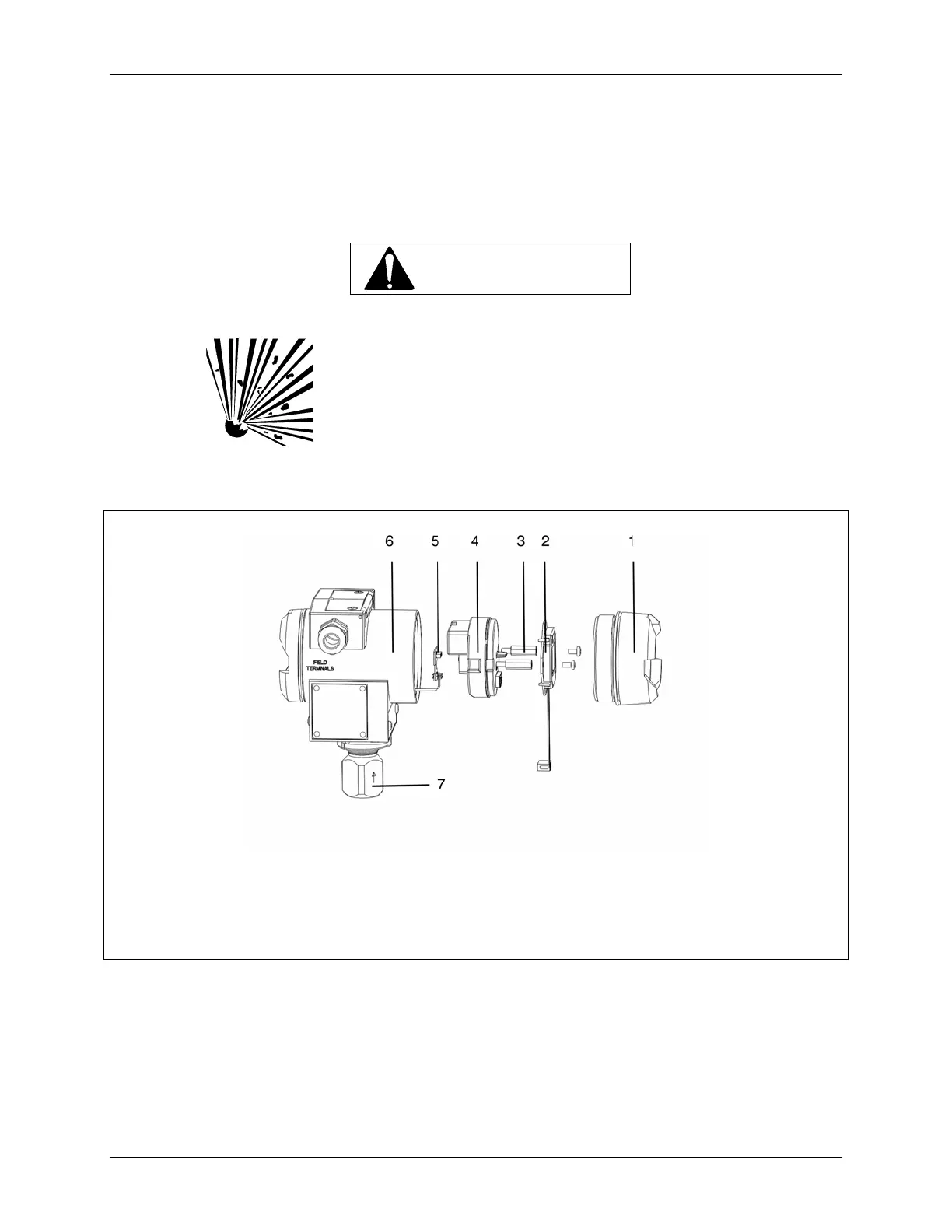
Refer to Section 7.0 for a list of tools. Figure 7-1 shows transmitter major assemblies.
WARNING
Explosion can cause death or serious injury.
In a Division 1 area, where an explosion-proof rating is
required, remove power from the transmitter before
removing either enclosure cap.
This device has a modular structure. Use only Siemens
authorized assemblies. When servicing, refer to the
instructions enclosed with replacement parts.
1
2
3
4
5
6
Enclosure cap with/without viewing glass
Digital Display
Threaded hex standoff
Electronics Module and display cable
Measuring Cell board
Enclosure
7
--
Measuring Cell (gauge construction shown;
includes measuring cell cable and measuring
cell board)
Terminal Board assembly (inside enclosure
cap adjacent to Field Terminals)
FIGURE 7-1 Transmitter Exploded View
The transmitter configuration must be reviewed after replacing either the electronics module (4) or the
measuring cell (7). The following table identifies the parameters that are stored and those that will need to
be entered.
 Loading...


