Appendix C - Elevation and Suppression Correction UMSITRPDS3-1
13-2 November 2005
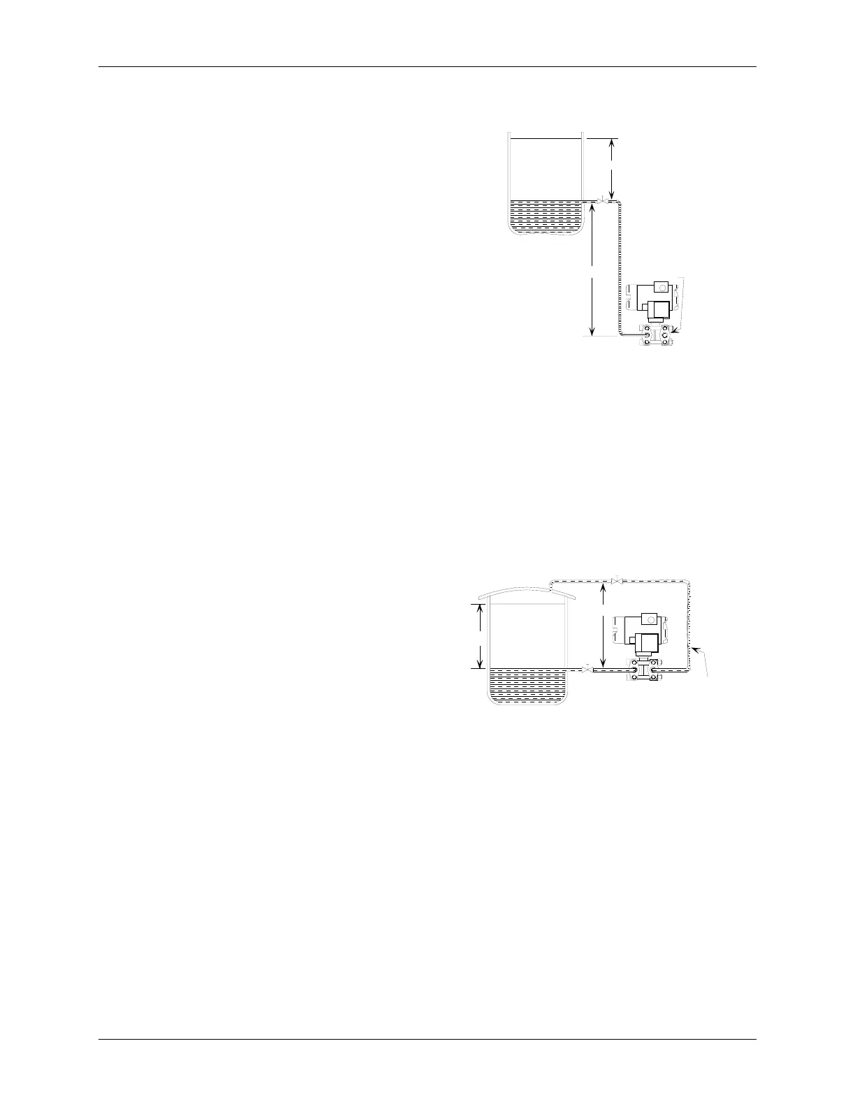
13.2 ELEVATION CALCULATION EXAMPLE
Figure C-3 shows a sample transmitter installation.
1. Calculate the differential pressure as follows.
Pressure
@DP
= (H × SpG)
High Side
- (H × SpG)
Low Side
where H = Height
2. Calculate the LRV when the tank is empty.
LRV = (120 × 1.0)
High Side
- (0 × 1.0)
Low Side
LRV = +120 inH
2
O
3. Calculate the URV.
URV = LRV + Span
URV = +120 + 100
URV = 220 inH
2
O
Therefore, transmitter range should be 120 to 220 inH
2
O.
13.3 SUPPRESSION CALCULATION EXAMPLE
Figure C-4 shows a sample transmitter installation.
1. Calculate the differential pressure as follows.
Pressure
@DP
= (H × SpG)
High Side
- (H × SpG)
Low Side
where H = Height
2. Calculate the LRV when the tank is empty.
LRV = (0 × 1.0)
High Side
- (100 × 1.0)
Low Side
LRV = -100 inH
2
O
3. Calculate the URV.
URV = LRV + Span
URV = -100 + 100
URV = 0 inH
2
O
Therefore, transmitter range should be -100 to 0 inH
2
O.
Max. Range
Min. Range
LP
HP
100"
Vent
H
2
O
SpG=1.0
120"
MG00363b
FIGURE 13-3 Elevation Calculation
Max. Range
Min. Range
LP
HP
Span
100"
H
2
O
SpG=1.0
MG00363b
LP Line
Filled with
Condensate
FIGURE 13-4 Suppression Calculation
 Loading...


