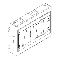
Installation
13
Building Technologies A6V10265083_a_en_--
Fire Safety & Security Products 03.2010
4.2 Mounting
Procedure
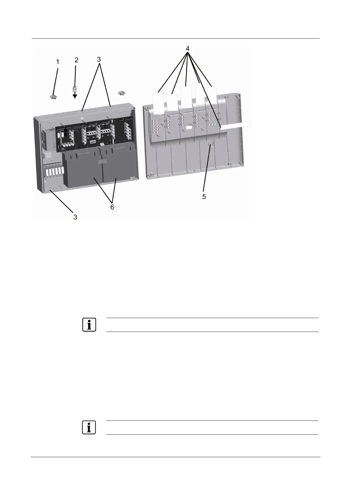
1. Remove front cover
2. Determine mounting location (not behind a door)
3. Mark position of mounting screws (use enclosed drilling template) and drill holes.
Installation accessories not included in cabinet:
– screws min. 4 x 50 mm
– plastic dowels
– c-shaped washers or lock washers
4. Mount chassis, if required with distance sleeves (1)
5. Break out cable entries (3) and mount cable glands (PG11) if required (2)
6. Insert inscription stripes (4)
Templates for inscription stripes are available as Word files at the hotline.
7. Remove the recess (5) if optional key switch is used
8. Insert batterie right (6)
9. Place the mid positioning battery holder
10. Insert battterie left
11. Connect all periphery devices (refer to page 14 – 19)
12. Put the secon
d battery holder on the left and screw it to lock both batteries
13. Set jumpers on main board (refer to page 14)
14. Commi
ssion system (refer to page 28)
15. Adapt the user functio
ns where required (refer to page 30 – 41)
16. Mount front cover
Protect the mounted unit with its shipping carton during construction phase by using the shipping
carton