Function and design
18
Building Technologies A6V10265083_a_en_--
Fire Safety & Security Products 03.2010
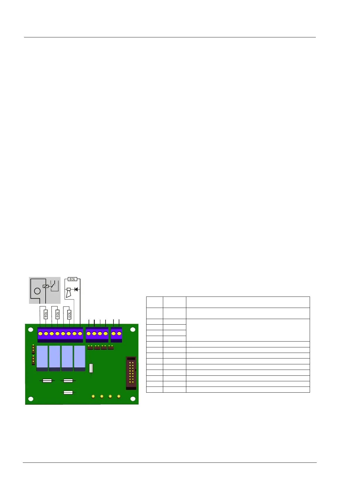
5.1.6 Control line extension card
Summery
The optional control line extension card features 4 monitored control outputs (con-
trol line 3 - 6). The following devices can be connected to the control outputs:
– Alarm devices like horns or flashlights
– Remote fire control installations
– RT devices
Functionality
The control outputs of control lines 3 – 6 have basically the same features as the
control outputs of control lines 1 and 2. For the control lines 3 - 6, attention should
be paid to the following:
– It is defined in programming step 5 when and how the control outputs are acti-
vated. In addition, each control output (control line 3 – 6) has a control
input (A – D). Input A is related with output 3 etc. An AND combination between
the setting in programming step 5 and the control input is enabled with a
Jumper, e.g. control output 3 shall only be activated in case of alarm 2 AND
driver output of zone 4 is active.
– Only control line 6 can be activated in case of a RT fault (see Step 5, activation
mode of control lines, option 14). If so, the Jumpers have to be set accordingly
(see table below).
– A LED is assigned to each control output. If the LED flashes, the corresponding
control output has either a line break or a short line.
Connection
– The board will be connected via the enclosed ribbon cable on the connector
CN10 to the main board.
– For power supply, a separate line has to run from the power supply card (termi-
nals on the right side of the card) to the control line extension card.
– If a control line is not used, it to has to be terminated with an EOL (FCE1002; in-
cluded in delivery).
The allocation of connection can be seen in the following board illustration.
Ref. Control
line
Setting / Function
PU1,
PU2
6
Pos. top = if option 14 progr. step 5 is selected
Pos. bottom = if option 1-13 in progr. step 5 is selected
PU3 5
PU4 6
PU5 4
PU6 3
OFF = zone-specific activation (control input used)
ON = common activation (control input not used)
DL1 3 LED flashing upon break or short
DL2 4 LED flashing upon break or short
DL3 5 LED flashing upon break or short
DL4 6 LED flashing upon break or short
CN1 Connector for flat cable to main board
F1 3 500 mAT Control line 3
F2 4 500 mAT Control line 4
F3 5 500 mAT Control line 5
F4 6 500 mAT Control line 6
PU4
PU3
PU5
PU6
PU2
PU1
DL1
DL2
DL3
DL4
A
B
C
D
+
-
+
-
+
-
+
-
+
-
CN1
1N4007
3
6
control input for line 6
control input for line 5
control input for line 4
control input for line 3
For zone-specific
activation only
input 24V supply
5
4
6
A
top
F1
F3
F4 F2
(A) Special Application: Line 6 used as remote control of state RT-fault
- Function: Line is activated in normal operating state and inactive in state system fault and on power off (FC10)
- Only possible with line 6
- Program option 14 in programming step 5
- Set jumper PU1 and PU2 on FCA1003 to position top
- Connect load between 350 … 2500 Ω (without EOL)