Operation and indicator elements, mode of operation (PMI)
24
Building Technologies A6V10265083_a_en_--
Fire Safety & Security Products 03.2010
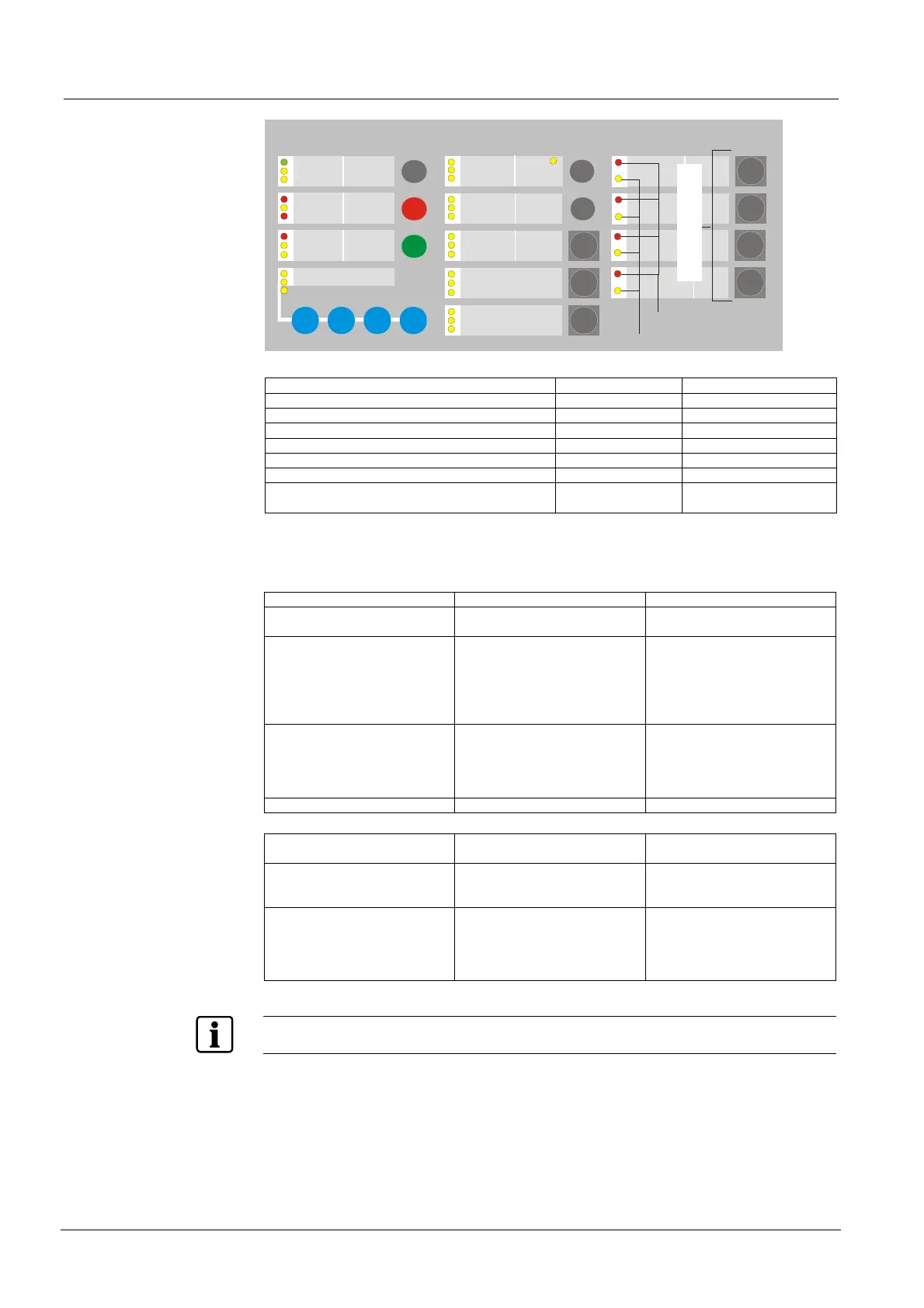
6.1.4 Zone indicators and keys
1
2
3
4
1
2
3
4
Zone LED red
Zone LED yellow
Zone key
Possible operating states zone LED zone red LED zone yellow
Alarm unacknowledged fast --
1st Alarm acknowledged slow --
Sub sequent alarm acknowledged (Alarm active) on --
Fault line break or line short 2) -- fast
Zone disabled -- 1) on
Zone in mode detector Test -- slow
Zone in mode detector Test with temporary alarm
activation (≤10s)
on slow
1) state disabled does not apply for line short alarms (option 2 step 10) if option 4 step 15 is pro-
grammed
2) Fire detection might be affected when a detection line fault condition appears. The fault shall be
repaired within a short time.
Possible action with key zone Function Result / subsequent function
1st activation zone is disabled Detector line set to 0 V
zone LED yellow = on
2nd activation zone is set to mode detector
test, allows to test each detector
via test alarm on site
zone LED yellow = slow
test-alarm activated:
detector alarm indicator on
zone LED red = on
automatic Reset of test alarm
after 10 sec.
2nd activation
and additionally
≤ 2 sec. activation of numeric
key 4
zone is set to mode detector test
and additionally
mode walk test is active
Same as above but
additionally
sounder control lines are
activated for 3 sec. with each
test-alarm
3rd activation to enable zone detector line in normal operation
Auxiliary functions with key
‘zone’
Function Result / subsequent function
Hold numeric key 1 followed by
pressing key zone
set zone to Alarm
(Alarm simulation)
Alarm is initiated according to
the setting of zone parameter
normal Alarm processing
Hold numeric key 2 followed by
pressing key zone
to set zone to Fault
(Fault simulation)
Fault is initiated
normal Fault processing
Except:
simulated zone Fault must be
Reset
In alarm state is the function of all zone keys are blocked.