Function and design
15
Building Technologies A6V10265083_a_en_--
Fire Safety & Security Products 03.2010
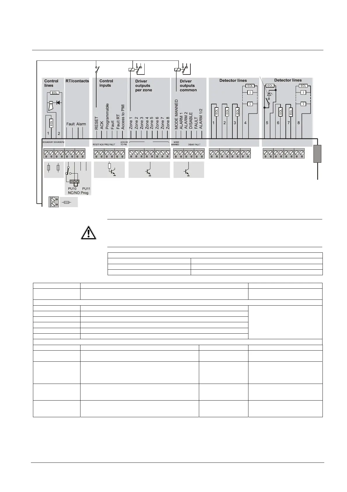
Peripheral connections
5.1.1 Mainboard
1N4007
++
++
++
++
++
++
++
++
+
+
+
__
__
__
__
_
_
LIN1 LIN5LIN2 LIN6LIN3 LIN7LIN4 LIN8
FAULT RT ALARM RT
OUT 24V
LIN1 LIN2 LIN3 LIN4 LIN5 LIN6
DRIVER
ALARM
LIN7 LIN8
1
FAULT
RT
ALARM
1/2
2
CL22
F1 F2
F4
Z-diode
5,6V
NOTE
Do not connect driver outputs directly to plus potential!
Outputs may be damaged.
In case of Fire the maximum current is, see I max b
Maximum nominal output current during battery charging, see I max. a
Detector and control lines that are not used must be terminated
detection line with FC10xx-A /-C resistor 3.9 kΩ
detection line with FC10xx-B EOL FCE1003-B
control line EOL FCE1002
Inputs Function / Application Remarks
Detector lines 1 - 8 – to process collective detectors
– various parameters (see Programming user functions)
Control inputs
Reset to reset system on Alarm (pulse); optional also on Fault
Ack to acknowledge system on Alarm and Fault (pulse)
Programmable see Step 16, programmable control input
Fault to initiate general Fault as long as positive potential is applied
Fault-RT to initiate RT-Fault as long as positive potential is applied
Access to PMI to provide operating access as long as positive potential is applied
– for internal and external use
– inputs always accessible (in-
dependent from state operating
access provided at the PMI)
Outputs Function / Application Load / rating Remarks
Power output 24 V To provide minus and positive potential for driver out-
puts and control inputs
– max. 500 mA for internal and external use
Control lines
Alarm devices
– To activate alarm devices (horn or flash light)
– active on Alarm 0, 1 and Alarm 2 until Reset
– various activation modes programmable
-> see Step 5, activation mode of control lines
– max. 500 mA/24 V
Relay contact
RT-Fault
– To provide state Fault to 3rd party systems
– active on RT-Fault until Acknowledge
– blocked with RT-Fault disabled
– max. 1 A/30 V
– type of contact NO
or NC
– NO/NC programmable via
jumper PU10
– also activated on system fault
Relay contact
RT-Alarm
– To provide state Alarm to 3rd party systems
– active on RT-Alarm (Alarm 2) until Reset
– blocked with RT-Alarm disabled
– max. 1 A/30 V
– type of contact NO
or NC
NO/NC programmable via jumper
PU11