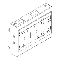
Operation and indicator elements, mode of operation (PMI)
25
Building Technologies A6V10265083_a_en_--
Fire Safety & Security Products 03.2010
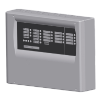
6.2 Display module
6.2.1 General
Optional display module that can be added on request in order to provide the func-
tions listed below.
Functions and displayed information
Alarm counter Counts up to 9999 alarms
– spontaneous display
– selectable RT-alarms only or RT-alarms and zone-alarms
– internal alarms and test alarms are not counted
Expiry time V1/V2 (min/s) Displays alarm delay
– spontaneous display on alarm
– shows the countdown of the time delays V1/V2
Clock Displays actual system time
– spontaneous display, possibly alternating with alarm counter
– mainly used to switch automatically from mode manned to unmanned
– also used for event memory
Event memory History for register events with date and time
– available upon polling
– registers alarms, related events and other states
– non-volatile memory that stores up to 320 events
Programming steps For commissioning
– displays the currently selected programming step
Service information The display module displays the following information
– last change of configuration (time and check sum)
– last test alarm (time and zone)
– version of firmware
Note:
The functions alarm counter, clock and event memory can be individually disabled
if not required (see Step 22, indicating mode display)
Display
mode
Battery operation and locked access . flashing dot (power save mode)
Counted RT alarms 0 2 5 7 --
Counted zone alarms 0 . 1. 3 . 4 flashing dots
Date and time (h/min) 1 4 . 3 8 flashing dot except for the year indication
Time not set or not correct 8 8 . 8 8 all digits flash
6.2.2 Poll event memory
System must be on operating access level 2 and in state non-alarm
Polling Input Display Remark
Newest event hold key Acknowledge then enter code 1122 E.001. always lowest event number
Year of event press numeric key 1 2003
Date of event press numeric key 2 05.11.
Hour and minute of event press numeric key 3 15.37
Next event (one event number
upwards)
press key Reset E.002. 2nd , 3rd, lowest event number etc.
Back to the newest event press numeric key 4 E.001. back to lowest event number
Exit press key Acknowledge at any step possible
Abort on alarm and 1min after last key operation
The type of event is always shown by the corresponding indicator at the PMI ac-
cording to table below.
Indicator PMI Type of event Remark
Red zone LED Alarm corresponding zone includes also simulated alarms, but no test alarms
LED 5
RT-Alarm
always registered as separate event
LED 7 System part disabled
LED 9
Fault
includes all types of fault events also simulated zone faults
LED 16
Evacuation