S5-95F
Expansion of Basic System with External //0s
How to Plug Input and Output
(1/0)
Modules into the Bus Units
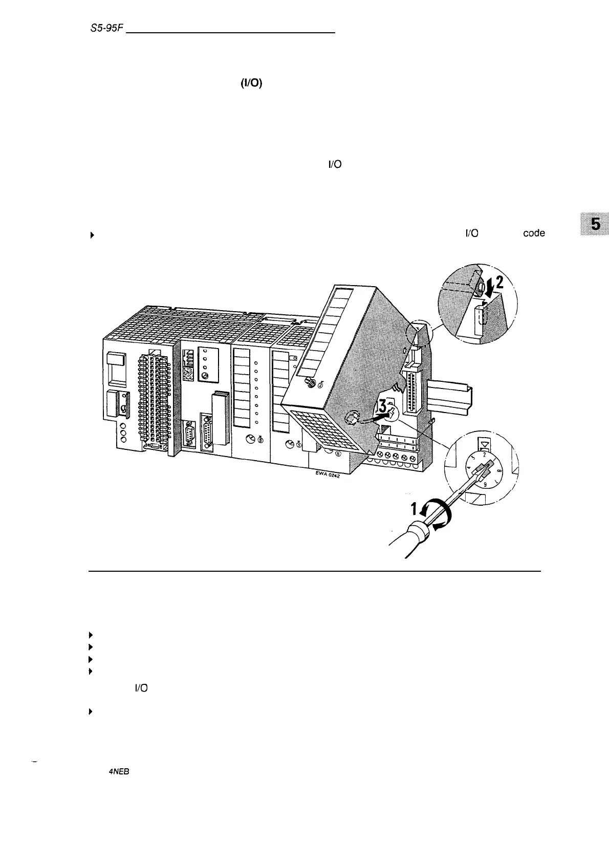
Before you mount an input or output module, you must set the coding element on the bus unit to
match the module type.
The coding element keeps you from confusing module types when ex-
changing modules.
Use the following information to set the coding element.
A code number is printed on the frontplate of every
1/0
module. The number is between two and
eight, depending on the particular module
type. There is a white, mechanical coding key located on
the back of each module.
The position of the coding key is determined by the module type and
cannot be changed. The bus unit has a mating component for each key, a white rotating
coding
element or “lock” (see Figure 5-3).
} Use a screwdriver
number.
to set the “lock” on the bus unit to the corresponding
li’O
module
\
la
m
o
0
0
Figure 5-3. Coding System to Prevent an Inadvertent Interchange of Modules
To attach the module, proceed as follows:
}
Hook the module onto the top of the bus unit.
} Swing the module down onto the bus unit.
} Press the module down firmly.
}
Tighten the hold-down screw on the front of the module to attach the module to the bus unit
To detach
1/0
modules:
}
Loosen the hold-down screw and swing the module up and out of the bus unit.
.
EWA
4NEB
8126210-02
5-3