An overview of system components
SIMOCODE pro
76 System Manual, 05/2019, A5E40507475002A/RS-AD/004
Accessories
Selection and ordering data: See also Catalog IC10 (https://www.siemens.com/ic10).
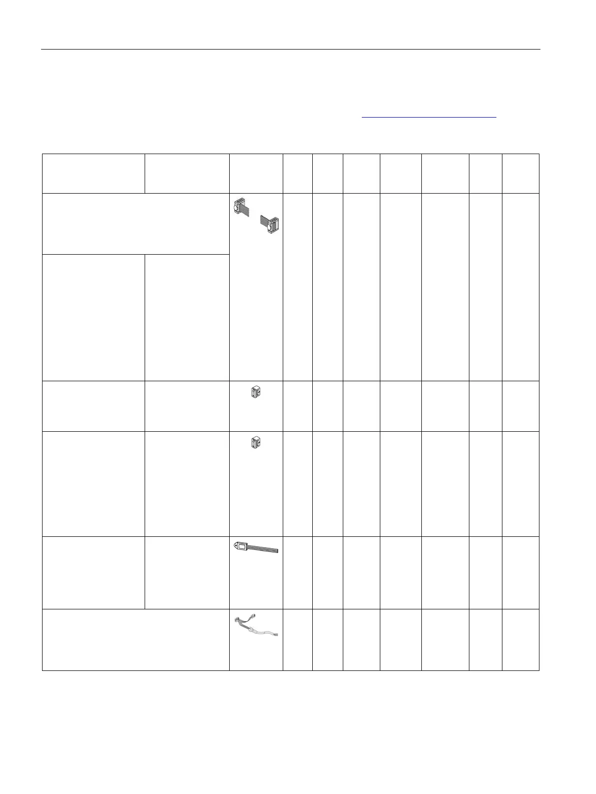
Table 7- 2 System components, accessories that can be connected
System component,
accessory
for connecting the basic unit, current
measuring module, current/voltage
measuring module, operator panel, and
✓ ✓ ✓ ✓ ✓ ✓ ✓
0.025 m ribbon
0.1 m ribbon
0.15 m ribbon
0.3 m ribbon
0.5 m ribbon
0.5 m round
1.0 m round
1.5 m round
3UF7930-0AA00-0
3UF7931-0AA00-0
3UF7935-0AA00-0
3UF7932-0AA00-0
3UF7932-0BA00-0
3UF7937-0BA00-0
.........
3UF7933-0BA00-0
For covering unused
system interfaces
3UF7950-0AA00-0
(light gray)
3RA6936-
✓ ✓ ✓ ✓ ✓ ✓ ✓
Backup of the full set of
parameters of a
SIMOCODE pro
system when the
device is replaced. If a
device is replaced,
parameter transfer
3UF7900-0AA00-0
(light gray)
3UF7900-0AA01-0
(titanium gray)
3UF7901-0AA00-0
(light gray)
3UF7901-0AA01-0
(titanium gray)
✓
✓
—
—
✓
✓
✓
✓
✓
✓
✓
✓
✓
✓
✓
1)
✓
1)
✓
✓
✓
✓
—
—
✓
✓
—
—
✓
✓
Storage and
initialization of device
parameters and device
addressing in motor
3UF7902-0AA00-0
— ✓ ✓ ✓
1)
✓ ✓ ✓
Connection of the basic unit and current or
current/voltage measuring module with the
initialization module when using the
— ✓ ✓ ✓ ✓ ✓ ✓