Configuration
5.4 Mounting
1FW3 complete torque motors
150 Configuration Manual, 08/2020, A5E46027705B AA
Shock load
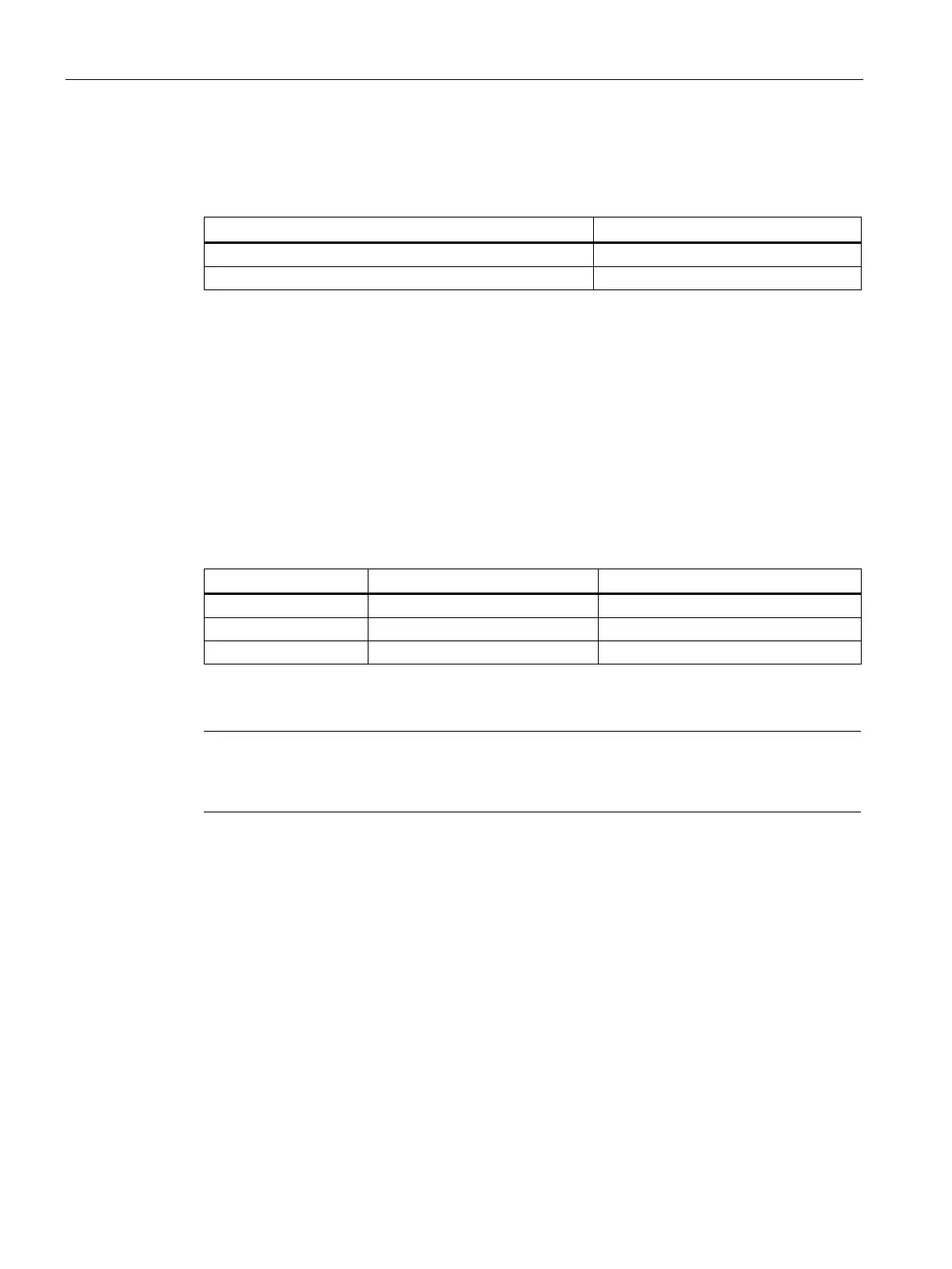
Table 5- 10 Shock load
Vibration acceleration a
peak
Max. permissible radial shock load
2
Max. permissible axial shock load
2
Evaluate the vibration acceleration as a peak value in the time domain in a frequency band
extending from 0 up to 2000 Hz. The measurement must be made at the DE flange (based
on DIN ISO 10816).
Appropriately adapt the measuring range if it is expected that noticeable vibration levels are
excited above 2000 Hz (e.g. as a result of gear tooth meshing frequencies). This does not
alter the maximum permissible values.
Mounting
A flange is used for mounting.
Table 5- 11 Flange mounting
1)
ISO 7092-16-300 HV (d2 = 30)
1)
Use screws of property class 10.9
Note
Screw locking
You must secure all screws as a result of the vibration and shock load.
Shaft adaptation
● A rigid connection between the motor and customer shaft is not permissible.
● Avoid distortion or overdetermining the bearings by precisely aligning the motor.
Axial and radial forces are not allowed.
● In operation, avoid any additional axial shock load to the motor shaft.
● Design the shaft adaptation so that there are no axial and radial forces (straight gearing
with splined shaft) and the appropriate play.
Axial and radial forces are not allowed.