Mechanical properties
3.6 Radial and axial forces
1FW3 complete torque motors
52 Configuration Manual, 08/2020, A5E46027705B AA
Table 3- 11 Solid shaft
The shaft version "solid shaft" can be ordered with a plain shaft end or with keyway
(according to DIN 6885-1).
Note
Shaft cover at NDE for the "hollow shaft" version
If the hollow through
-shaft is not used by the customer and must be sealed at the NDE for
touch protection reasons, the motor can be supplied with a shaft cover at the NDE. Ordering
options: Ord
er code T20.
See the dimension drawings for further details.
Direction of rotation
The positive direction of rotation is clockwise when viewing the drive end (flange side).
3.6 Radial and axial forces
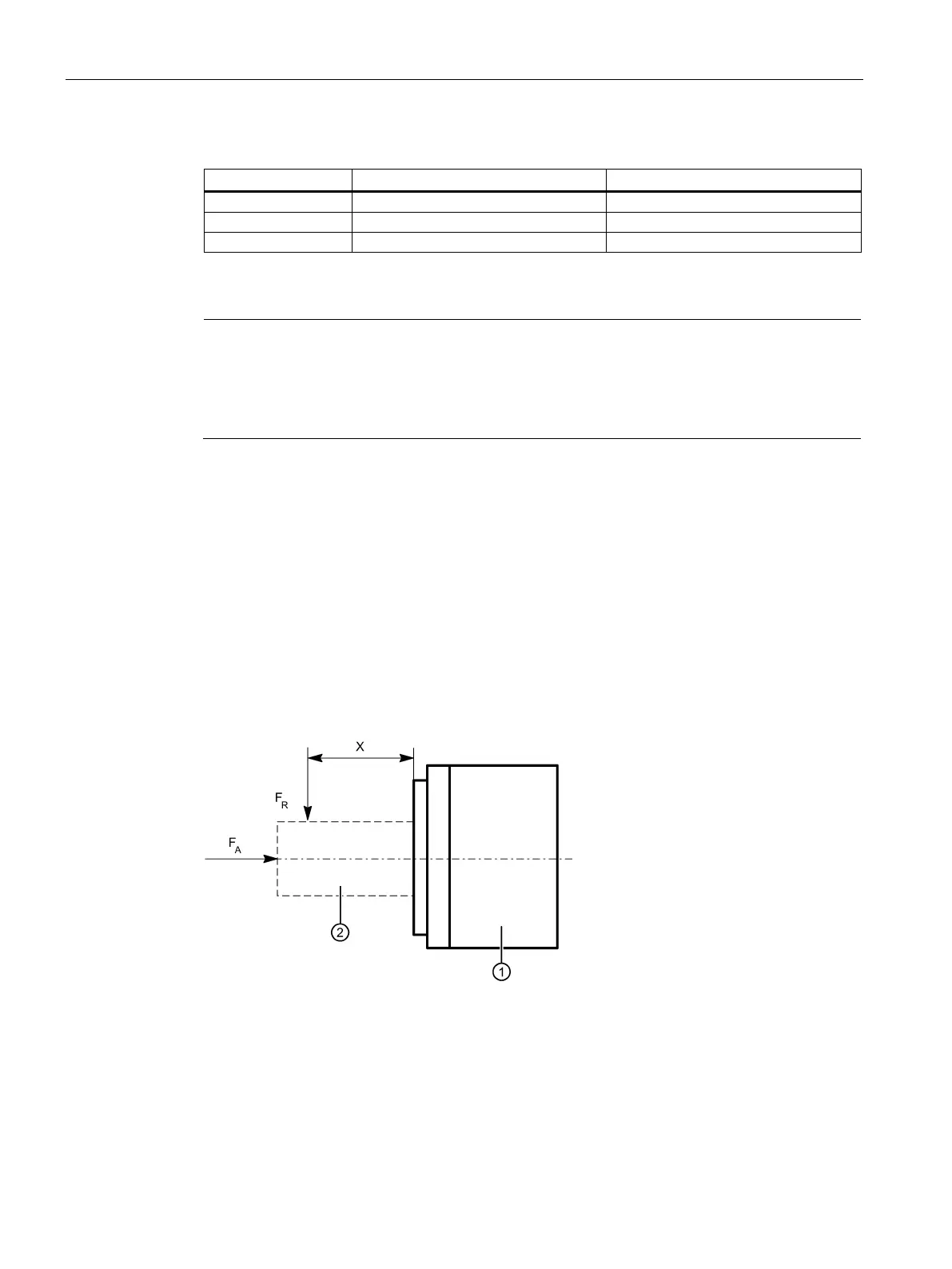
Point of application of radial forces F
R
at the torque motor
● for average operating speeds
● for a nominal bearing change interval of 20000 h
Dimension X in mm: Distance between the point of application of force F
R
and the shaft shoulder of
Figure 3-5 Point of application of radial force F
R
and axial force F
A