For diagnostic purposes, the X127 LAN interface features a green and a yellow LED. These
LEDs indicate the following status information:
Table 3-7 LED statuses for the X127 LAN interface
LED Color Status Description
Link port - Off Missing or faulty link
Green Continuous light 10 or 100 Mbit link available
Activity port - Off No activity
Yellow Flashing light Sending or receiving
3.1.2.7 X140 serial interface (RS 232)
An external display and operator device for operator control/parameterization can be
connected via the serial interface. The interface is located on the underside of the Control Unit.
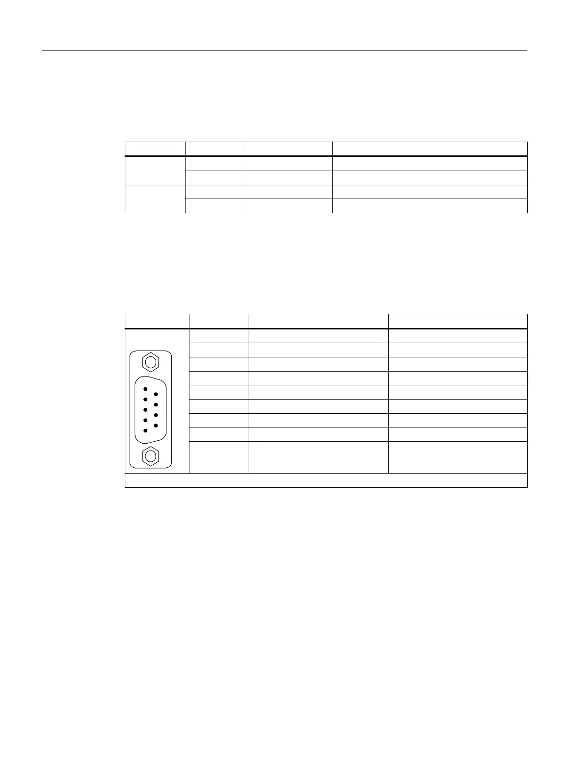
Table 3-8 X140 serial interface (RS232)
Pin Signal name Technical data
1 Reserved, do not use -
2 RxD Receive data
3 TxD Send data
4 Reserved, do not use -
5 Ground Ground reference
6 Reserved, do not use -
7 Reserved, do not use -
8 Reserved, do not use -
9 Reserved, do not use -
Connector type: 9-pin SUB D connector
Control Units
3.1 Control Unit CU320-2 PN (PROFINET)
Supplementary component descriptions
20 Manual, 06/2019

 Loading...


