5.2.3 Meaning of the LEDs
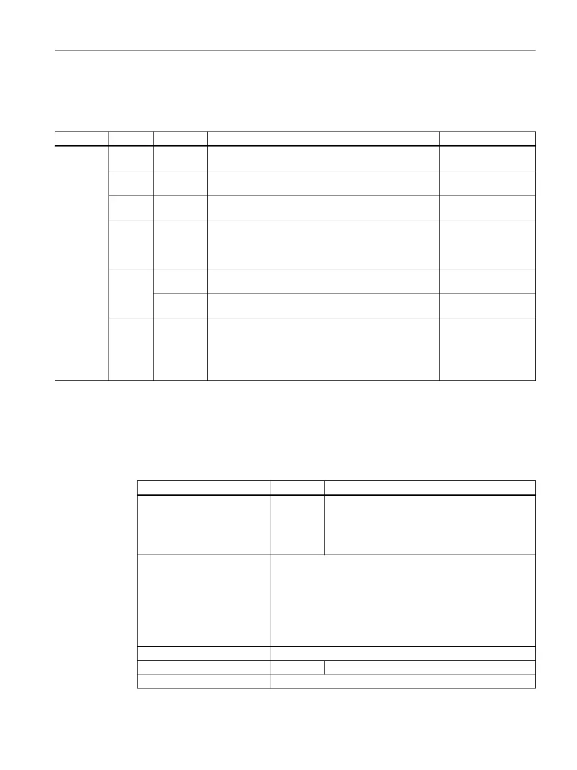
Table 5-20 Meanings of the LEDs on the Terminal Module TM31
LED Color Status Description, cause Remedy
READY - Off The electronics power supply is missing or outside the per‐
missible tolerance range.
–
Green Continuous
light
The component is ready for operation. Cyclic DRIVE-CLiQ
communication is taking place.
–
Orange Continuous
light
DRIVE-CLiQ communication is being established. –
Red Continuous
light
This component has at least one fault.
Note:
The LED is activated regardless of whether the correspond‐
ing messages have been reconfigured.
Remove and acknowl‐
edge the fault.
Green/re
d
Flashing
light 0.5 Hz
Firmware is being downloaded. –
Flashing
light 2 Hz
Firmware download has been completed. The system waits
for POWER ON.
Carry out a POWER
ON.
Green/
orange
or
Red/
orange
Flashing
light
Component recognition via LED is activated
1)
.
Note:
Both options depend on the LED status when component
recognition is activated via p0154 = 1.
–
1)
See List Manual for the parameter to activate the recognition of components via LED
5.2.4 Technical data
Table 5-21 Technical data
6SL3055-0AA00-3AAx Unit Value
Electronics power supply
Voltage
Current (without DRIVE-CLiQ
and digital outputs)
Power loss
V
DC
A
DC
W
24 (20.4 … 28.8)
0.5
< 10
Response time The response time of the digital inputs/outputs and the
analog inputs/outputs comprise the following:
● Response time on the component itself
(approx. 1/2 DRIVE-CLiQ cycle).
● Transfer time via the DRIVE-CLiQ connection
(approx. 1 DRIVE-CLiQ cycle).
● Evaluation on the Control Unit (see function diagram).
PE/ground connection At the housing with M4/1.8 Nm screw
Weight kg 1
Degree of protection IP20
Terminal Modules
5.2 Terminal Module TM31
Supplementary component descriptions
Manual, 06/2019 71

 Loading...


