5.2.2.8 X530 digital inputs
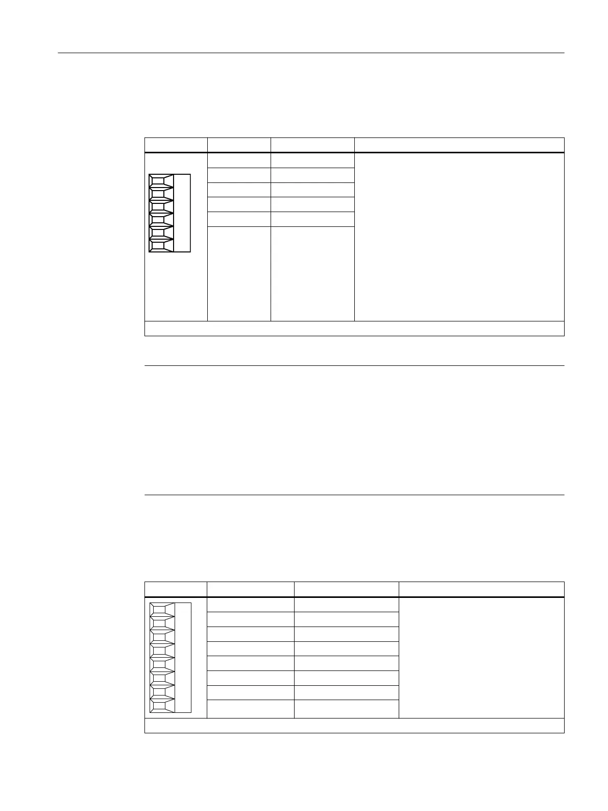
Table 5-16 X530: Digital inputs
Terminal Designation
1)
Technical data
1 DI 4 Voltage: -3 … +30 V DC
Electrical isolation: Yes
Reference potential: M2
Input characteristic acc. to IEC 61131-2, type 1
Input voltage (including ripple)
"1" signal: 15 … 30 V
"0" signal: -3 … +5 V
Input current
at 24 V DC: typ. 9 mA
at <0.5 mA: Signal "0" reliably detected
Input delay
for "0" → "1": typ. 50 µs/max. 100 µs
for "1" → "0": typ. 130 µs/max. 150 µs
2 DI 5
3 DI 6
4 DI 7
5 M2
6 M
Type: Screw terminal 1
1)
DI: digital input; M: electronics ground; M2: reference potential
Note
Ensuring the function of digital inputs
An open input is interpreted as "low".
To enable the digital inputs (DI) to function, terminal M2 must be connected.
This is achieved by using one of the following measures:
1. Providing the ground reference of the digital inputs
2. A jumper to terminal M
Note: This removes isolation for these digital inputs.
5.2.2.9 X540 auxiliary voltage for the digital inputs
Table 5-17 X540: Auxiliary voltage for digital inputs
Terminal Designation Technical data
8 +24 V Voltage: +24 V DC
Max. total load current of +24 V auxili‐
ary voltage for terminals X540 and
X541 combined: 150 mA
7 +24 V
6 +24 V
5 +24 V
4 +24 V
3 +24 V
2 +24 V
1 +24 V
Type: Screw terminal 1
Terminal Modules
5.2 Terminal Module TM31
Supplementary component descriptions
Manual, 06/2019 67

 Loading...


