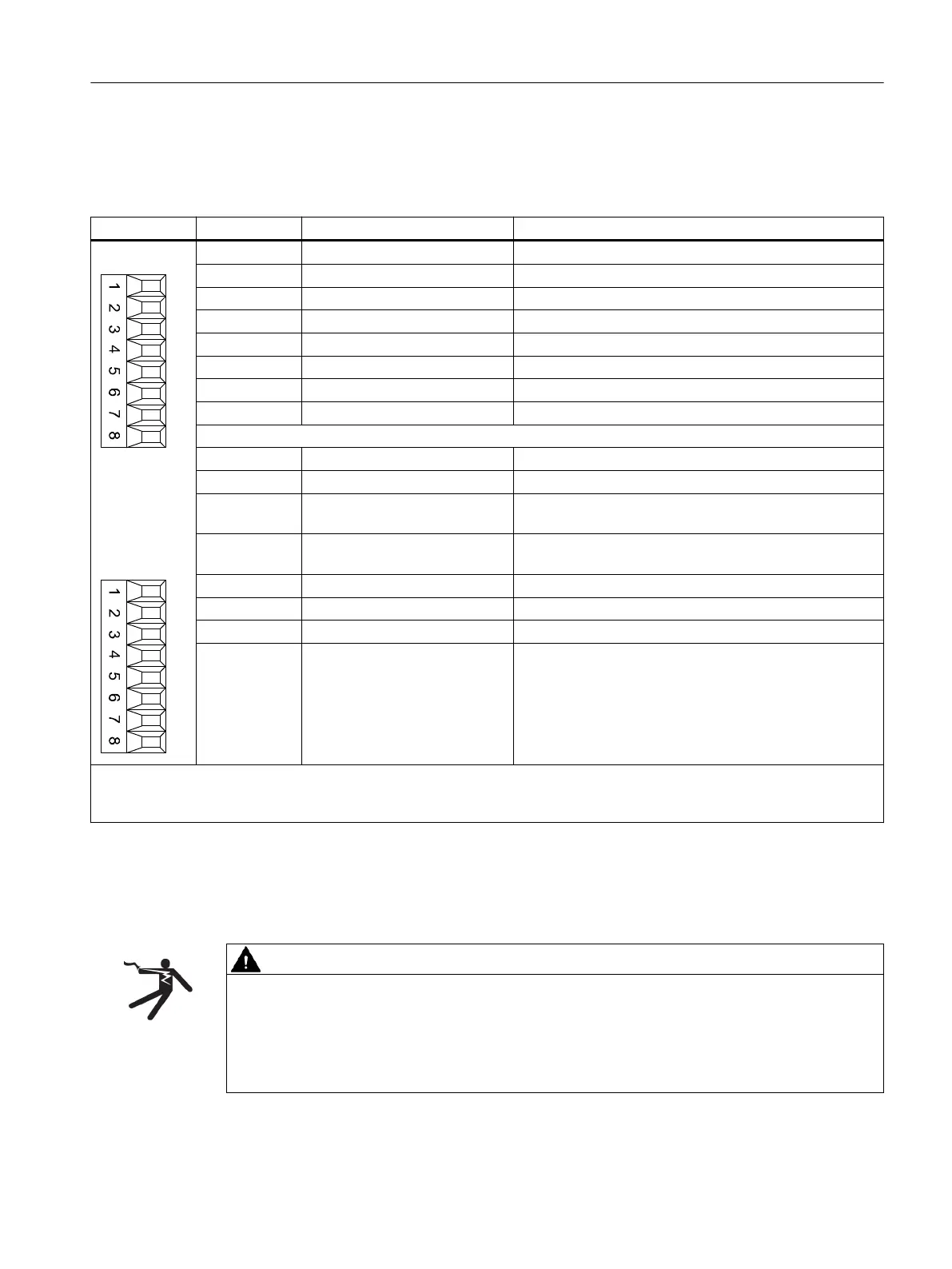
7.2.4 X521 / X531 alternative encoder system interface
Table 7-3 X521/X531: Alternative encoder system interface
Pin Designation Technical data
X521
X531
1 A Incremental signal A
2 A* Inverse incremental signal A
3 B Incremental signal B
4 B* Inverse incremental signal B
5 R Reference signal R
6 R* Inverse reference signal R
7 CTRL Control signal
8 M Ground
1 P_Encoder 5 V / 24 V Encoder power supply
2 M_Encoder Ground, encoder power supply
3 - Temp
1)
Motor temperature sensing KTY84-1C130 (KTY-)
Temperature sensor KTY84-1C130 / PTC
4 + Temp
1)
Motor temperature sensing KTY84-1C130 (KTY+)
Temperature sensor KTY84-1C130 / PTC
5 Clock SSI clock
6 Clock* Inverse SSI clock
7 Data SSI data
8 Data* Inverse SSI data
Max. connectable cross-section: 1.5 mm
2
Measuring current via the temperature sensor connection: 2 mA
When unipolar HTL encoders are used, A*, B*, and R* on the terminal block must be jumpered with M_Encoder (X531)
2)
.
1)
Accuracy of temperature measurement:
- KTY: ±7°C (including evaluation)
- PTC: ±5℃ (including evaluation)
2)
Because the physical transmission media is more robust, the bipolar connection should always be used. The unipolar
connection should only be used if the encoder type does not output push-pull signals.
WARNING
Danger to life through electric shock due to unconnected cable shields
Hazardous touch voltages can occur through capacitive cross-coupling due to unconnected
cable shields.
● Attach the cable shield to the component for the encoder system connection at the
terminals.
Sensor Module Cabinet-Mounted SMC30
7.2 Interface description
Supplementary component descriptions
Manual, 06/2019 91

 Loading...


