5.1.2.4 X521 bidirectional digital inputs/outputs
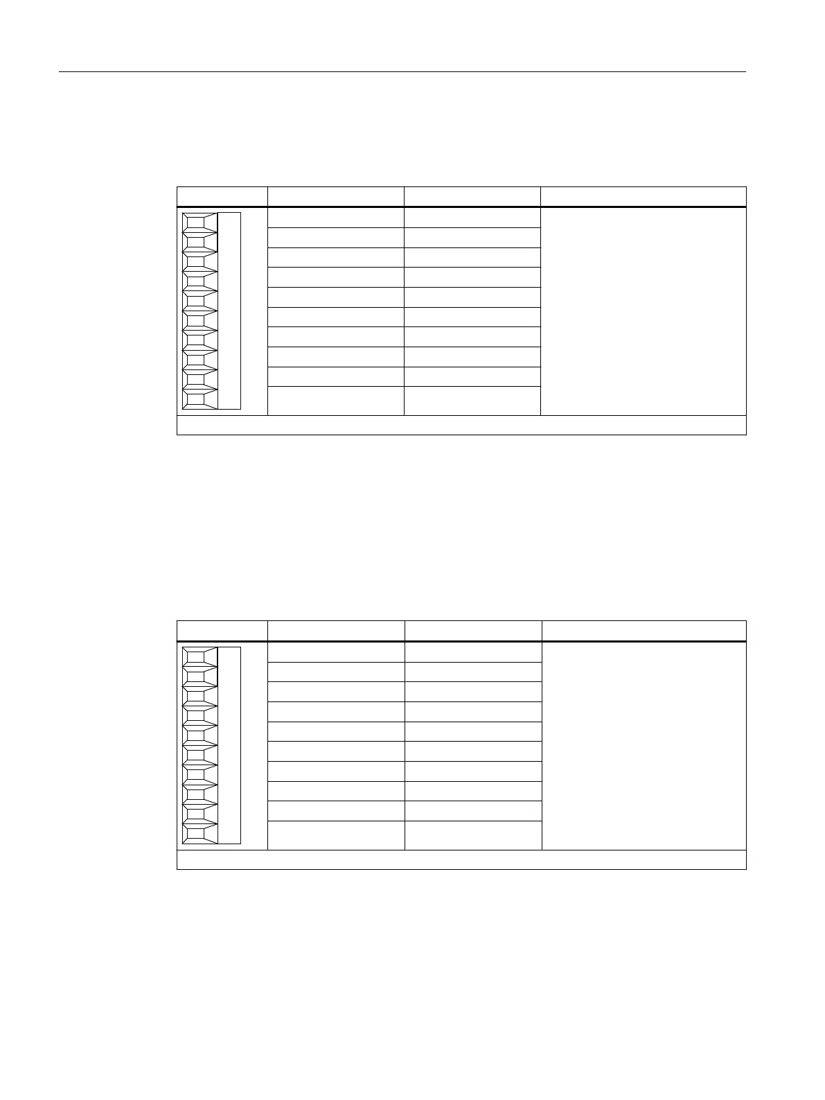
Table 5-4 X521 digital inputs/outputs
Terminal Designation
1)
Technical data
1 L2+ See Chapter "Technical data".
2 DI/DO 8
3 DI/DO 9
4 DI/DO 10
5 DI/DO 11
6 DI/DO 12
7 DI/DO 13
8 DI/DO 14
9 DI/DO 15
10 M2 (GND)
Type: Screw terminal 1
1)
L2+: The 24 V DC infeed for DI/DO 8 to 15 (second potential group) must always be connected if at
least one DI/DO of the potential group is used as an output.
M2: The ground reference for DI/DO 8 to 15 (second potential group) must always be connected if at
least one DI/DO of the potential group is used as an input or output.
DI/DO: Bidirectional digital input/output
5.1.2.5 X522 bidirectional digital inputs/outputs
Table 5-5 X522 digital inputs/outputs
Terminal Designation
1)
Technical data
1 L3+ See Chapter "Technical data".
2 DI/DO 16
3 DI/DO 17
4 DI/DO 18
5 DI/DO 19
6 DI/DO 20
7 DI/DO 21
8 DI/DO 22
9 DI/DO 23
10 M3 (GND)
Type: Screw terminal 1
1)
L3+: The 24 V DC infeed for DI/DO 16 to 23 (third potential group) must always be connected if at least
one DI/DO of the potential group is used as an output.
M3: The ground reference for DI/DO 16 to 23 (third potential group) must always be connected if at
least one DI/DO of the potential group is used as an input or output.
DI/DO: Bidirectional digital input/output
Terminal Modules
5.1 Terminal Module TM15
Supplementary component descriptions
58 Manual, 06/2019

 Loading...


