6.2.3 X520 analog inputs/temperature sensor
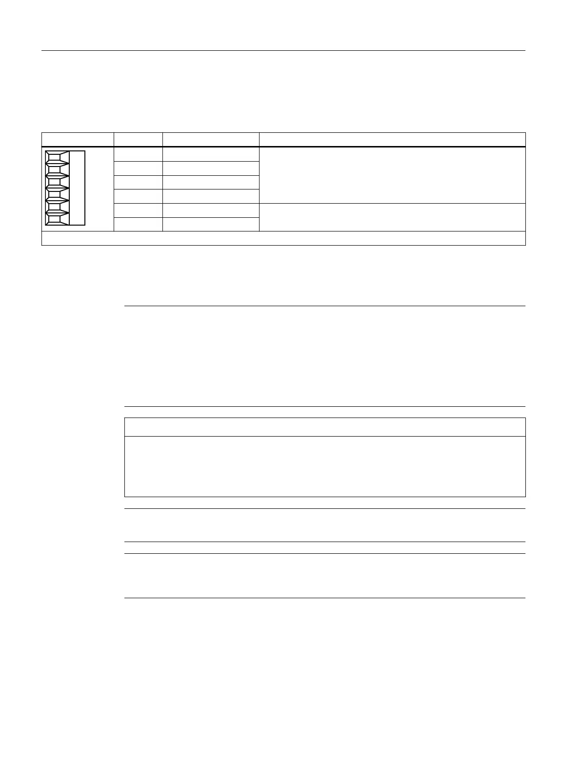
Table 6-3 X520: Analog inputs/temperature sensor
Terminal Designation Technical data
1 AI 0- 2 analog differential inputs
Voltage: -10 … +10 V; Ri > 100 kΩ
Resolution: 12 bits + sign
2 AI 0+
3 AI 1-
4 AI 1+
5 + Temp
1)
KTY84-130 / Pt1000 / PTC temperature sensors
Measuring current through temperature sensor connection: 2 mA
6 - Temp
1)
Type: Screw terminal 1
1)
Accuracy of the temperature measurement:
- KTY: ±7 °C (including evaluation)
- Pt1000: ±5 °C (Pt1000 tolerance class B according to EN 60751 including evaluation)
- PTC: ±5 °C (including evaluation)
Note
Permissible voltage values
The common mode range must not be violated in order to avoid incorrect analog-digital
conversion results. The following voltages are permissible:
● Input voltage: ±30 V (destruction limit)
● Common mode voltage: ±10 V with respect to ground potential (increased errors when
exceeded)
NOTICE
Damage to motor in the event of incorrectly connected KTY temperature sensor
If a KTY temperature sensor is connected with incorrect polarity, it is not possible to detect
when the motor overheats. Overheating can cause damage to the motor.
● Connect a KTY temperature sensor with the correct polarity.
Note
In order to minimize noise emission, shielded cables should be used.
Note
The maximum cable length for a shielded cable applied on both sides to the temperature sensor
and to the analog inputs is 30 m.
Voltage Sensing Module VSM10
6.2 Interface description
Supplementary component descriptions
82 Manual, 06/2019

 Loading...


