5.1.4 Technical data
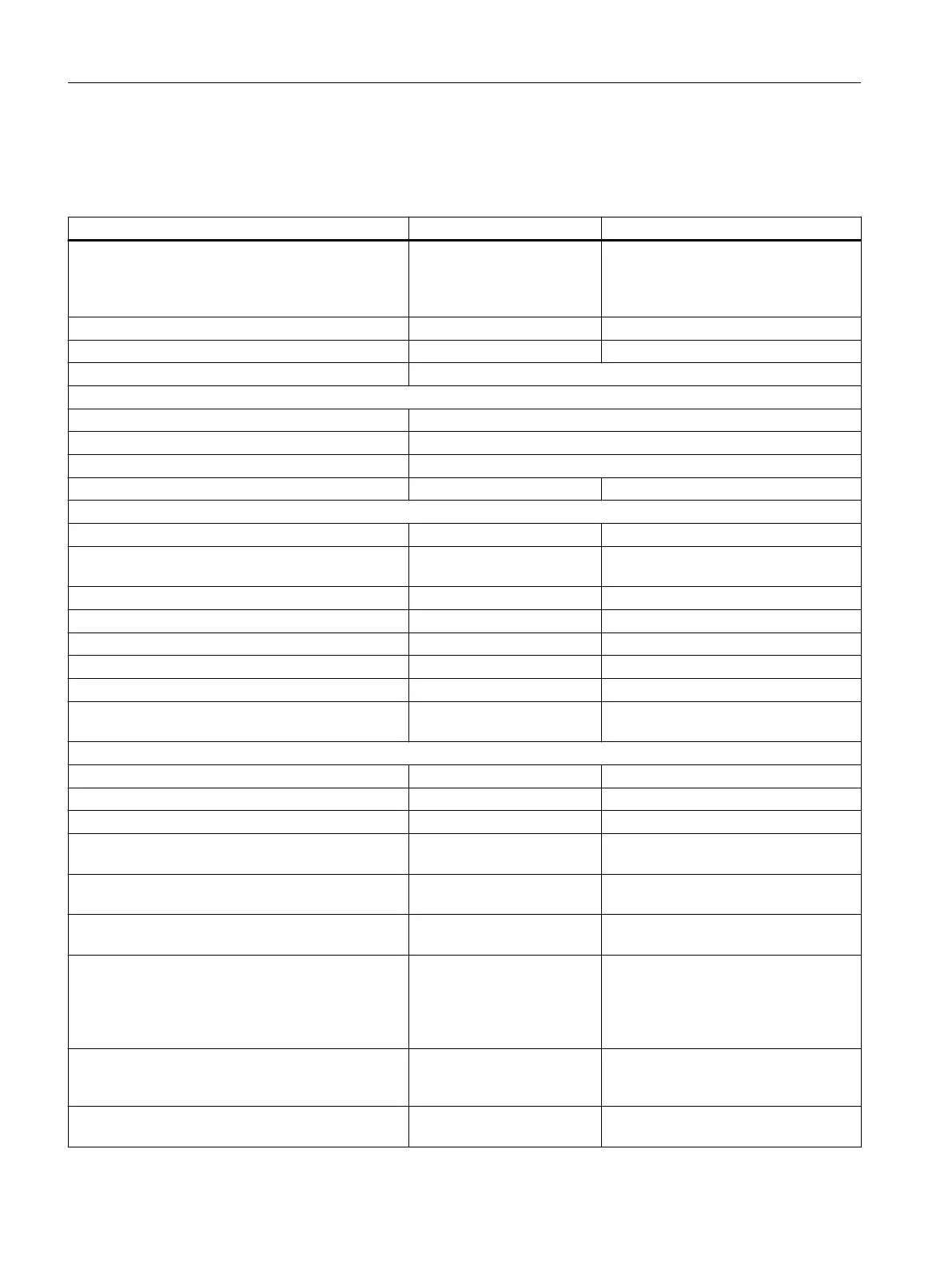
Table 5-8 Technical data
6SL3055-0AA00-3FAx Unit Value
Electronics power supply
Voltage
Current (without DRIVE-CLiQ or digital outputs)
Power loss
V
DC
A
DC
W
24 (20,4 … 28,8)
0,15
< 3
Ambient temperature up to an altitude of 2,000 m °C 0 … 60
Storage temperature °C -40 … +85
Relative humidity 5 … 95 %, no condensation
I/O
Digital inputs/outputs Can either be parameterized as DI or DO
Number of digital inputs/outputs 24
Electrical isolation Yes, in groups of 8
Max. cable length m 30
Digital inputs
Voltage V
DC
-30 … +30
Low-level (an open digital input is interpreted as
"low")
V
DC
-30 … +5
High level V
DC
15 … 30
Input Impedance kΩ 2,8
Current consumption (at 24 V DC) mA 11
Max. voltage in OFF state V
DC
5
Current in OFF state mA 0.0 … 1.0 (per channel)
Typical input delay of the digital inputs μs "0" → "1": 50
"1" → "0": 100
Digital outputs (continued-short-circuit-proof)
Voltage V
DC
24
Max. load current per digital output A
DC
0,5
Output delay (ohmic load)
Typical μs "0" → "1": 50
"1" → "0": 150
Maximum μs "0" → "1": 100
"1" → "0": 225
Min. output pulse
(100% amplitude, 0.5 A with resistive load)
μs 125 (typ.)
350 (max.)
Switching frequency
For resistive load
For inductive load
For lamp load
Maximum lamp load
Hz
Hz
Hz
W
Max. 100
Max. 0.5
Max. 10
5
Max. switching frequency
(100% amplitude, 50%/50% duty cycle;
with 0.5 A and a resistive load)
kHz 1 (typ.)
Voltage drop in ON state V
DC
0.75 (max.) for maximum load in all cir‐
cuits
Terminal Modules
5.1 Terminal Module TM15
Supplementary component descriptions
60 Manual, 06/2019

 Loading...


