7.2.2 X500 DRIVE-CLiQ interface
Table 7-1 X500: DRIVE-CLiQ interface
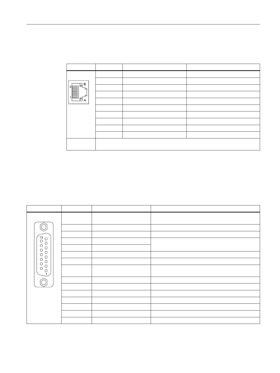
Pin Signal name Technical data
1 TXP Transmit data +
2 TXN Transmit data -
3 RXP Receive data +
4 Reserved, do not use -
5 Reserved, do not use -
6 RXN Receive data -
7 Reserved, do not use -
8 Reserved, do not use -
A Reserved, do not use -
B M (0 V) Electronics ground
Connector
type
DRIVE-CLiQ socket
The blanking cover for the DRIVE-CLiQ port is included in the scope of delivery.
Blanking covers (50 x) Article No:: 6SL3066-4CA00-0AA0
7.2.3 X520 encoder system interface
Table 7-2 X520: Encoder system interface
Pin Signal name Technical data
1 + Temp
1)
Motor temperature sensing KTY84-1C130 (KTY+)
Temperature sensor KTY84-1C130 / PTC
2 Clock SSI clock
3 Clock* Inverse SSI clock
4 P encoder 5 V / 24 V Encoder power supply
5 P encoder 5 V / 24 V
6 P sense Sense input encoder power supply
7 M encoder (M) Ground, encoder power supply
8 - Temp
1)
Motor temperature sensing KTY84-1C130 (KTY-)
Temperature sensor KTY84-1C130 / PTC
9 M sense Ground sense input
10 R Reference signal R
11 R* Inverse reference signal R
12 B* Inverse incremental signal B
13 B Incremental signal B
14 A* / data* Inverted incremental signal A/inverted SSI data
15 A / data Incremental signal A/SSI data
Sensor Module Cabinet-Mounted SMC30
7.2 Interface description
Supplementary component descriptions
Manual, 06/2019 89

 Loading...


