5.1.2.2 X500/X501 DRIVE-CLiQ interfaces
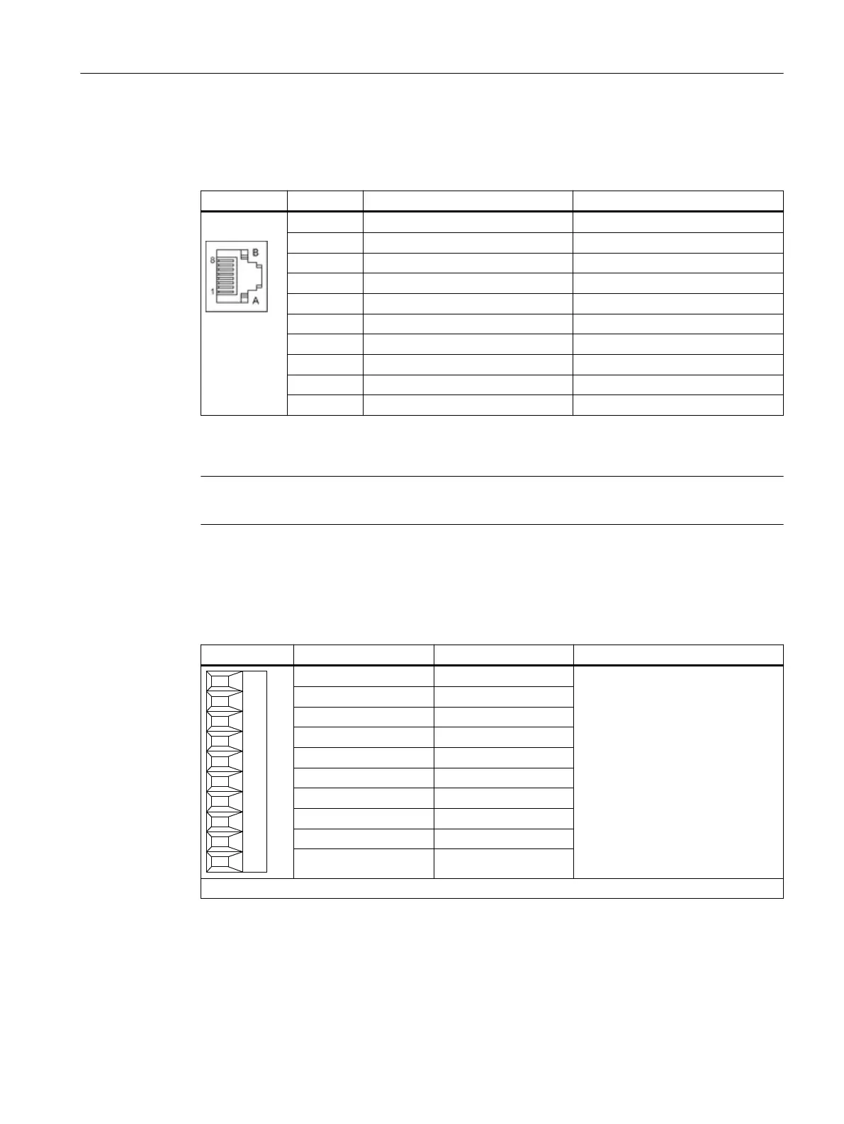
Table 5-2 X500/X501 DRIVE-CLiQ interfaces
Pin Signal name Technical data
1 TXP Transmit data +
2 TXN Transmit data -
3 RXP Receive data +
4 Reserved, do not use -
5 Reserved, do not use -
6 RXN Receive data -
7 Reserved, do not use -
8 Reserved, do not use -
A + (24 V) Power supply
B M (0 V) Electronics ground
The blanking covers for the DRIVE-CLiQ interfaces are included in the scope of delivery.
Blanking covers (50 x) Article No.: 6SL3066-4CA00-0AA0
Note
The maximum DRIVE-CLiQ cable length is 100 m.
5.1.2.3 X520 bidirectional digital inputs/outputs
Table 5-3 X520 digital inputs/outputs
Terminal Designation
1)
Technical data
1 L1+ See Chapter "Technical data".
2 DI/DO 0
3 DI/DO 1
4 DI/DO 2
5 DI/DO 3
6 DI/DO 4
7 DI/DO 5
8 DI/DO 6
9 DI/DO 7
10 M1 (GND)
Type: Screw terminal 1
1)
L1+: The 24 V DC infeed for DI/DO 0 to 7 (first potential group) must always be connected if at least
one DI/DO of the potential group is used as an output.
M1: The ground reference for DI/DO 0 to 7 (first potential group) must always be connected if at least
one DI/DO of the potential group is used as an input or output.
DI/DO: Bidirectional digital input/output
Terminal Modules
5.1 Terminal Module TM15
Supplementary component descriptions
Manual, 06/2019 57

 Loading...


