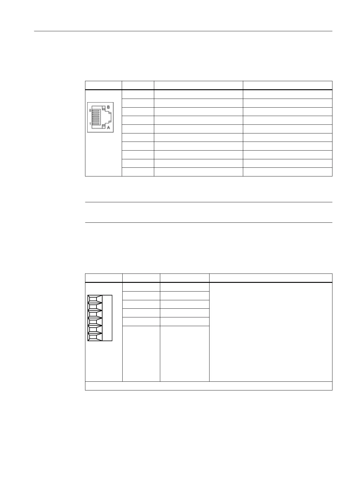
5.2.2.2 X500/X501 DRIVE-CLiQ interfaces
Table 5-10 X500/X501 DRIVE-CLiQ interfaces
Pin Signal name Technical data
1 TXP Transmit data +
2 TXN Transmit data -
3 RXP Receive data +
4 Reserved, do not use -
5 Reserved, do not use -
6 RXN Receive data -
7 Reserved, do not use -
8 Reserved, do not use -
A + (24 V) Power supply
B M (0 V) Electronics ground
The blanking covers for the DRIVE-CLiQ interfaces are included in the scope of delivery.
Blanking covers (50 x) Article No.: 6SL3066-4CA00-0AA0
Note
The maximum DRIVE-CLiQ cable length is 100 m.
5.2.2.3 X520 digital inputs
Table 5-11 X520: Digital inputs
Terminal Designation
1)
Technical data
1 DI 0 Voltage: -3 … +30 V
Electrical isolation: Yes
Reference potential: M1
Input characteristic acc. to IEC 61131-2, type 1
Input voltage (including ripple)
"1" signal: 15 … 30 V
"0" signal: -3 … +5 V
Input current
at 24 V DC: typ. 9 mA
at <0.5 mA: Signal "0" reliably detected
Input delay
for "0" → "1": typ. 50 µs max. 100 µs
For "1" → "0": typ. 130 µs/max. 150 µs
2 DI 1
3 DI 2
4 DI 3
5 M1
6 M
Type: Screw terminal 1
1)
DI: Digital input; M: Electronics ground; M1: reference potential
Terminal Modules
5.2 Terminal Module TM31
Supplementary component descriptions
Manual, 06/2019 63

 Loading...


