3.1.2.8 X150 P1/P2 PROFINET
The PROFINET interfaces can be operated isochronously.
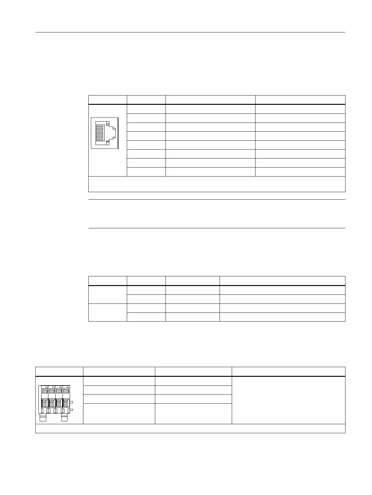
Table 3-9 X150 P1 and X150 P2 PROFINET
Pin Signal name Technical data
1 RXP Receive data +
2 RXN Receive data -
3 TXP Transmit data +
4 Reserved, do not use -
5 Reserved, do not use -
6 TXN Transmit data -
7 Reserved, do not use -
8 Reserved, do not use -
Connector type: RJ45 socket
Cable type: PROFINET
Note
The PROFINET interfaces support Auto MDI(X). It is therefore possible to use both crossed
and uncrossed cables to connect the devices.
For diagnostic purposes, the two PROFINET interfaces are equipped with a green and a yellow
LED. These LEDs indicate the following status information:
Table 3-10 LED states at the X150 P1/P2 PROFINET interface
LED Color Status Description
Link port - Off Missing or faulty link
Green Continuous light 10 or 100 Mbit link available
Activity port - Off No activity
Yellow Flashing light Data is being received or sent at port x
3.1.2.9 Measuring socket
Table 3-11 Measuring socket with mounted PC board connector
Socket Function Technical data
M Ground Voltage: 0… 5 V
Resolution: 8 bits
Load current: max. 3 mA
Continuous short-circuit proof
The reference potential is terminal M
T0 Measuring terminal 0
T1 Measuring terminal 1
T2 Measuring terminal 2
PCB plug connector from Phoenix Contact, type: ZEC 1.0/ 4-ST-3.5 C1 R1.4, Article number: 1893708
Control Units
3.1 Control Unit CU320-2 PN (PROFINET)
Supplementary component descriptions
Manual, 06/2019 21

 Loading...


