7
Transformations 08.97
7.1 Three
four and five-axes transformation: TRAORI
7
840D
NCU 572
NCU 573
840Di
Siemens AG 2000. All rights reserved
7-220
SINUMERIK 840D/840Di/810D/FM-NC Programming Guide Advanced (PGA)
−
04.00 Edition
7.1 Three, four and five-axes transformation: TRAORI
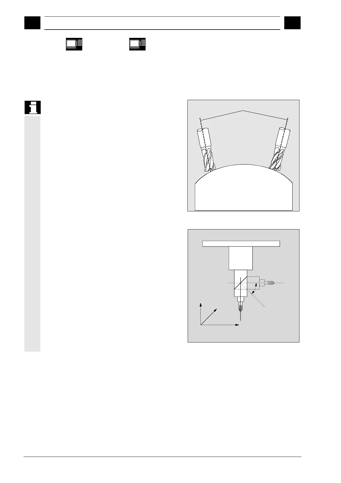
In order to achieve optimal cutting conditions in the
machining of curved surfaces, the approach angle of
the tool must be variable.
The machine design used to achieve this is stored in
the axis data.
Tool axis
Universal milling head
Here three linear axes (X, Y, Z) and two orientation
axes define the setting angle and machining point of
the tool. One of the two orientation axes is applied
as an inclined axis – in many cases, and in example
A'
−
positioned at a 45° angle.
The axis sequence of the orientation axes and the
direction of orientation of the tool are set via machine
data as a function of the machine kinematics. In the
examples on the right, the arrangements are illustrated
by machine kinematics CA!
A
,
Z
Y
X
C
Universal millin
head, version 1