8
Tool Offsets 04.00
8.8 Toolholder kinematics
8
840D
NCU 572
NCU 573
840Di
Siemens AG 2000. All rights reserved
8-296
SINUMERIK 840D/840Di/810D/FM-NC Programming Guide Advanced (PGA)
−
04.00 Edition
8.8 Toolholder kinematics
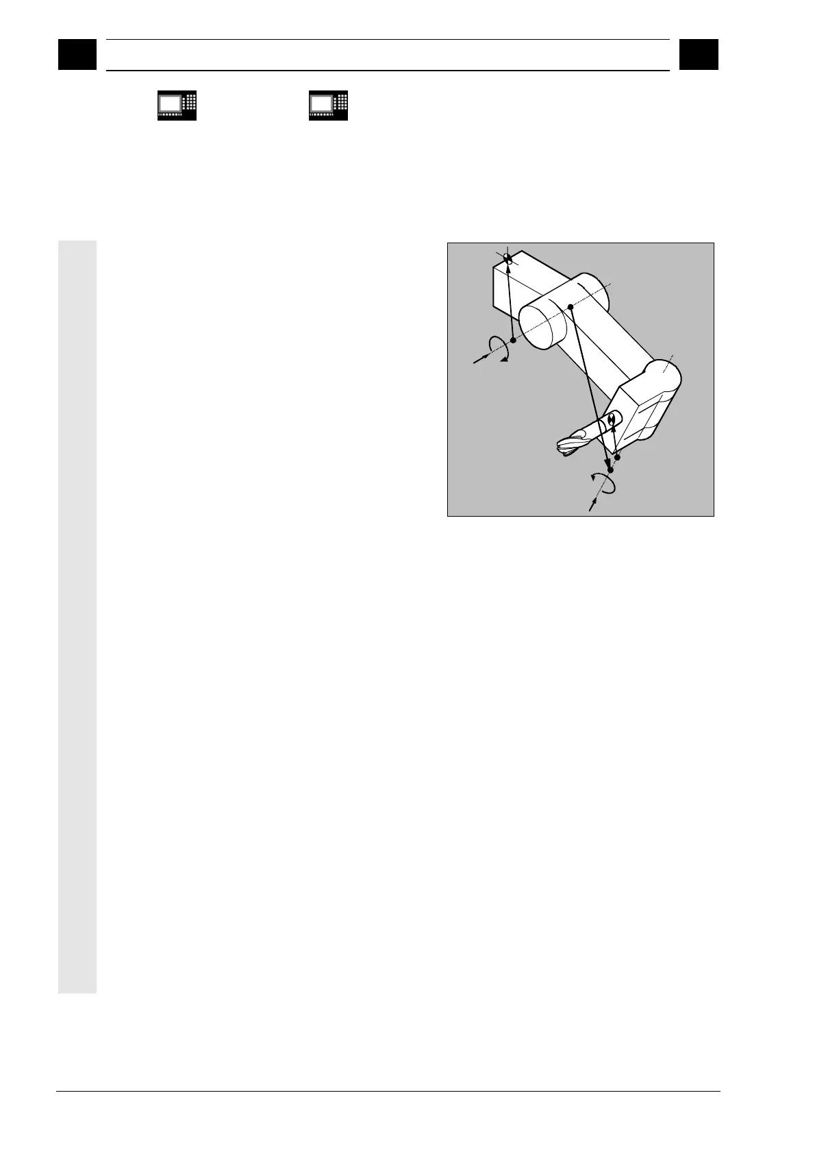
The toolholder kinematics with up to two rotary axes is
programmed by means of 17 system variables (see
also Programming Guide Advanced) $TC_CARR1[m]
to $TC_CARR17[m]. The description of the toolholder
consists of:
•
the vectorial distance between the first rotary axis
and the toolholder reference point l
1
, the vectorial
distance between the first and the second rotary
axis l
2
, the vectorial distance between the second
rotary axis and the tool reference point l
3
;
•
the reference vectors of both rotary axes
V1,V2;
•
the rotary angles
α
1
,
α
2
around both axes. The
rotation angles are counted in viewing direction of
the rotary axis vectors, positive, in clockwise
direction of rotation.
Resolved kinematics as of SW 5.3
For machines with resolved kinematics (both the tool
and the part can rotate), the system variables have
been extended to include the entries $TC_CARR18[m]
to $TC_CARR23[m] are are described as follows:
The rotatable part consisting of:
•
the vector distance between the second rotating
axis v
2
and the reference point of a rotatable tool
table l
4
of the the third rotary axis.
The rotary axes consisting of:
•
the two channel identifiers for the reference to the
rotary axes v
1
and v
2
. These posiitons are
accessed as required to determine the oritentation
of the orientable toolholder.
The permissible types of kinematics consisitng of:
•
Type of kinematics T: Only tool can rotate.
•
Type of kinematics P: Only part can rotate.
•
Type of kinematics M: Tool and part can rotate
V
1
V
2
α
1
α
2
l
1
l
2
l
3

 Loading...


