8
Tool Offsets 04.00
8.5 Activate 3D tool offsets
8
840D
NCU 572
NCU 573
840Di
Siemens AG 2000. All rights reserved
8-282
SINUMERIK 840D/840Di/810D/FM-NC Programming Guide Advanced (PGA)
−
04.00 Edition
Mill shapes, tool data
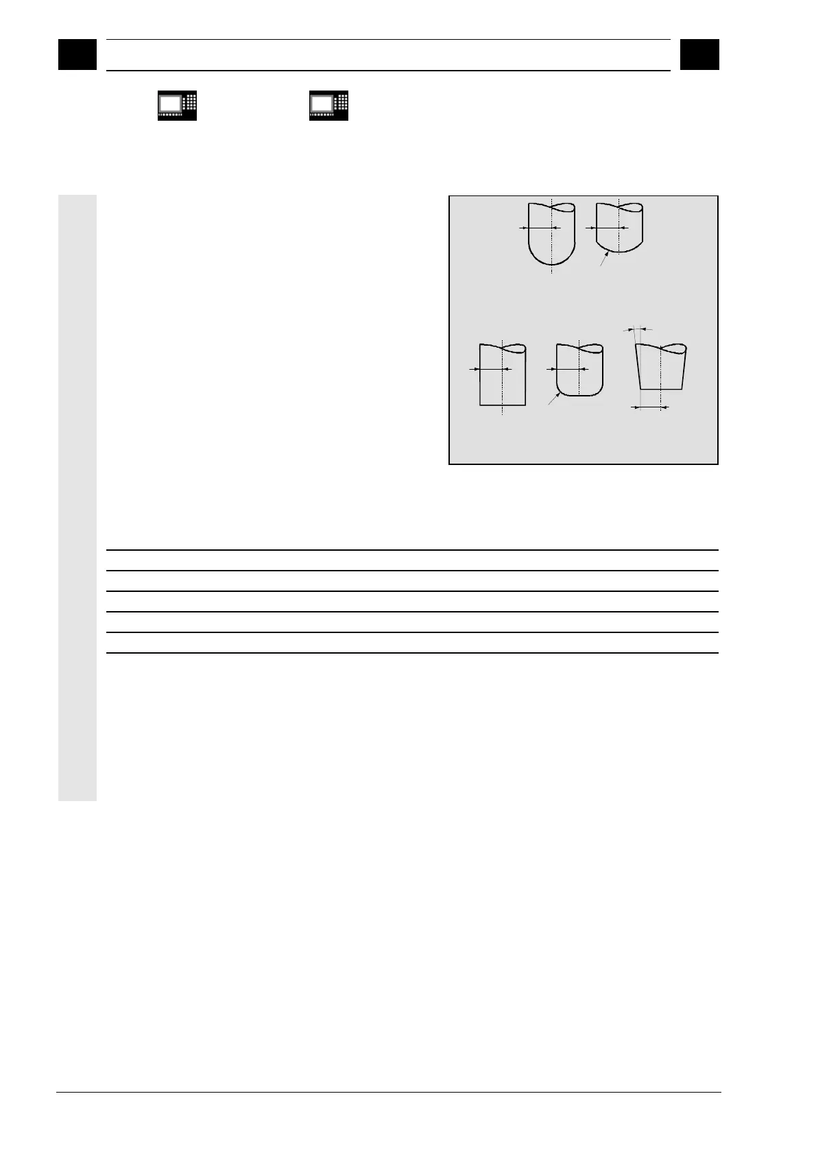
The table below gives an overview of the tool shapes
which may be used in face milling operations as well
as tool data limit values.
The shape of the tool shaft is not taken into
consideration – the tools 120 and 155 are identical in
their effect.
If a different type number is used in the NC program
than the one listed in the table, the system
automatically uses tool type 110 die-sinking cutter.
An alarm is output if the tool data limit values are
violated.
Cylindr. die
sinker
(type 110)
R
Ballhead
cutter
(type 111)
R
r
End mill
(type 120, 130)
R
End mill with
corner round.
(type 121, 131)
R
r
Truncated cone mill
(type 155)
R
a
Milling tool type
Type No. R r a
Cylindrical miller 110 >0 X X
Ball end mill 111 >0 >R X
End mill, angle head cutter 120, 130 >0 X X
End mill, angle head cutter with corner rounding 121, 131 >r >0 X
Truncated cone mill 155 >0 X >0
X=is not evaluated
Tool length compensation
The tool tip is the reference point for length
compensation (intersection longitudinal
axis/surface).