1
02.98 Flexible NC Programming
1.14 Interru
t routine
1
840D
NCU 571
840D
NCU 572
NCU 573
810D
840Di
Siemens AG 2000. All rights reserved
SINUMERIK 840D/840Di/810D/FM-NC Programming Guide Advanced (PGA)
−
04.00 Edition
1-73
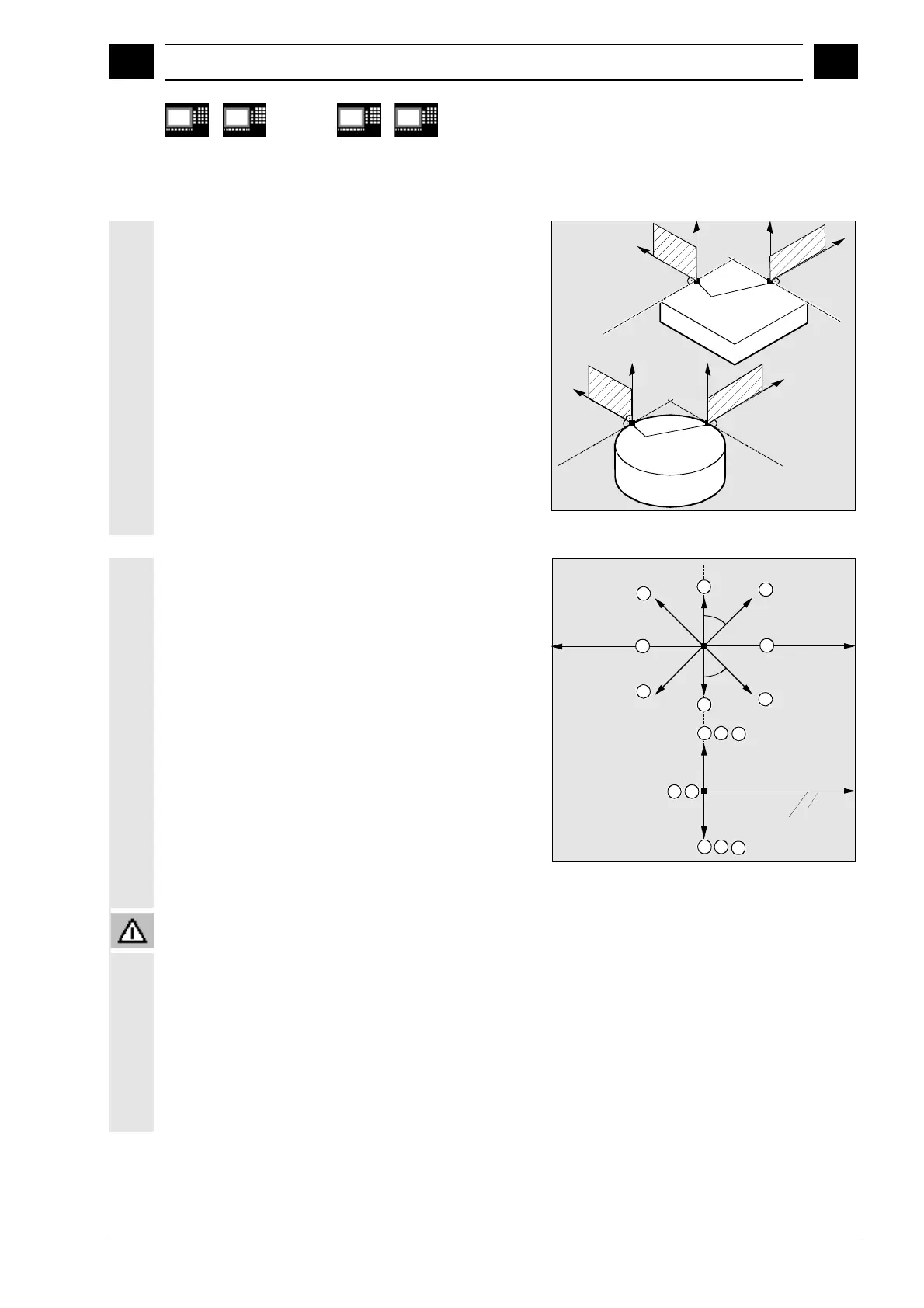
Reference plane for describing the
traversing directions
At the point of application of the tool to the
programmed contour, the tool is clamped at a plane
which is used as a reference for specifying the lift-off
movement with the corresponding code number.
The reference plane is derived from the longitudinal
tool axis (infeed direction) and a vector positioned
perpendicular to this axis and perpendicular to the
tangent at the point of application of the tool.
E
Point of
application
Tangent
Tangent
Tangent
Tangent
Point of
application
Code number with traversing directions,
overview
The code numbers and the traversing directions in
relation to the reference plane are shown in the
diagram on the right.
ALF=0 deactivates the liftfast function.
45°
45°
5
1
8
2
8
4
G41
G42
2
6
3
4
7
1
3
5
6
7
Plan view
Traversing direction
View in
traversing
direction
Feed axis
Please note:
The following codes should not be used when tool
radius compensation is active:
Codes 2, 3, 4 with G41
Codes 6, 7, 8 with G42.
In these cases, the tool would approach the contour
and collide with the workpiece.