Home
Siemens
Controller
SIPROTEC 5
Hardware Description
Page 106
Siemens SIPROTEC 5 - Page 106
302 pages
Manual
To Next Page
To Next Page
To Previous Page
To Previous Page
Loading...
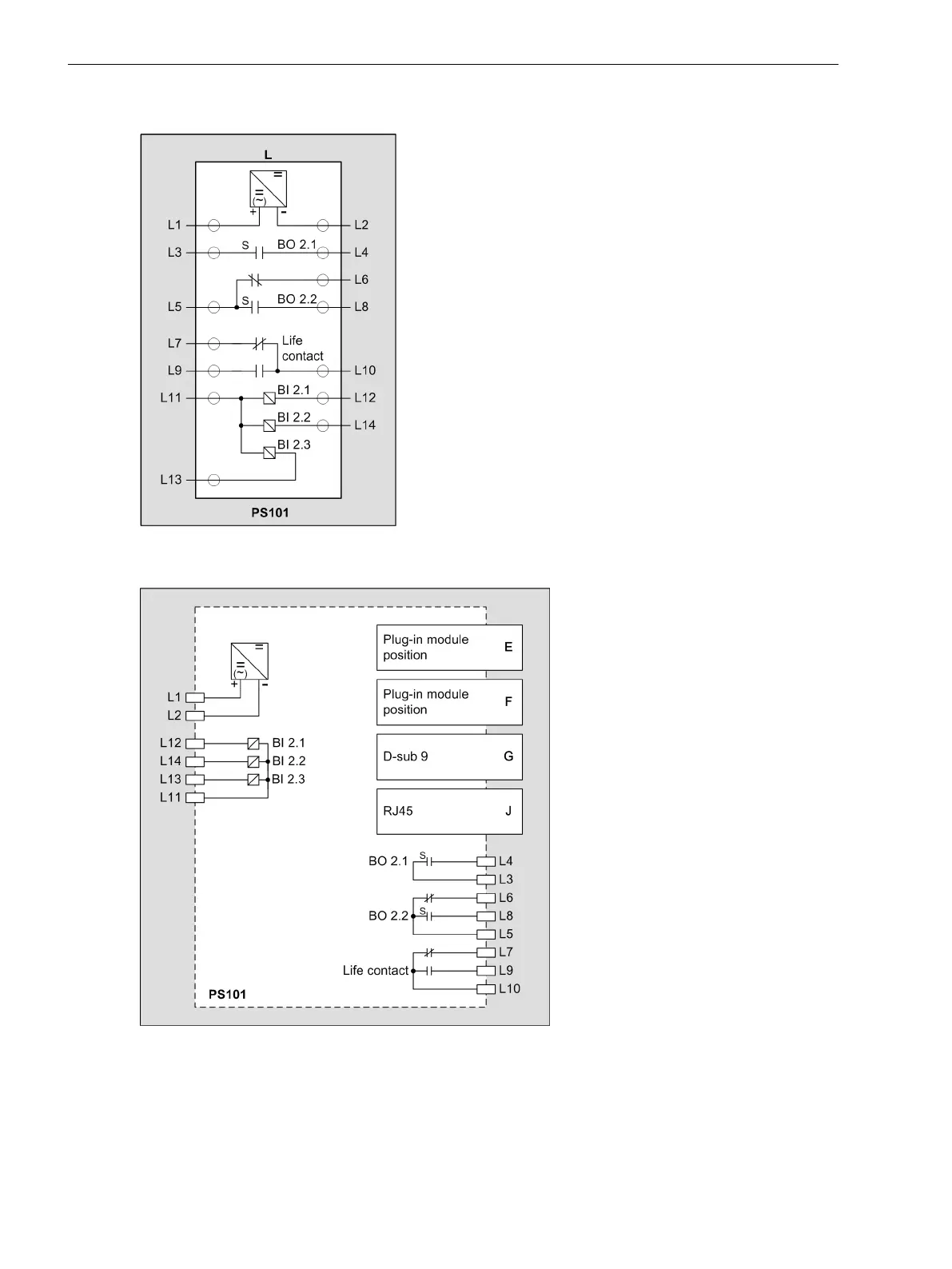
[cdio230x-030713-01.tif, 1, en_US]
Figure 3-61
IO230 – Terminal Diagram
Electronic Modules
3.2 Input and Output Modules of the Modular Devices
106
SIPROTEC 5, Hardware Description, Manual
C53000-G5040-C002-N, Edition 04.2022
105
107
Table of Contents
Main Page
Default Chapter
3
Preface
3
Siprotec
5
Open Source Software
7
Table of Contents
9
1 Introduction
15
Advantages of SIPROTEC 5
16
Modular Systems and Hardware Characteristics
17
2 Forms of Devices and On-Site Operation Panels
19
Flush-Mounting Devices
20
Description
20
Surface-Mounted Devices with Integrated On-Site Operation Panel
28
Description of the Modular Device
28
Description of the Non-Modular Surface-Mounting Device
30
Surface-Mounted Devices with Detached On-Site Operation Panel
34
Description
34
On-Site Operation Panels
37
Description
37
Overview of Operating Elements and Display Elements
38
3 Electronic Modules
43
Power-Supply Modules of the Modular Devices
44
Application Sheet of the Power-Supply Modules of the Modular Devices
44
Power-Supply Module PS201
44
Description
44
Terminals
45
Power-Supply Module PS203
48
Description
48
Terminals
49
Plug-In Module Assembly with Integrated Power Supply CB202
51
Description
51
Terminals
52
Input and Output Modules of the Modular Devices
54
Function Description of the Input and Output Modules of the Modular Devices
54
Input and Output Module IO201
55
Description
55
Terminals
55
Input and Output Module IO202
57
Description
57
Terminals
58
Input and Output Module IO203
60
Description
60
Terminals
61
Input and Output Module IO204
63
Description
63
Terminals
64
Input and Output Module IO205
66
Description
66
Terminals
67
Input and Output Module IO206
69
Description
69
Terminals
70
Input and Output Module IO207
72
Description
72
Terminals
72
Input and Output Module IO208
74
Description
74
Terminals
75
Input and Output Module IO209
77
Description
77
Terminals
78
Input and Output Module IO210
80
Description
80
Terminals
81
Input and Output Module IO211
83
Description
83
Terminals
84
Input and Output Module IO212
86
Description
86
Terminals
87
Input and Output Module IO214
89
Description
89
Terminals
90
Input and Output Module IO215
92
Description
92
Terminals
92
Input Module IO230
93
Description
93
Terminals
93
Input and Output Module IO231
96
Description
96
Terminals
96
Input Module IO233
98
Description
98
Terminals
99
Input and Output Module PB201
101
Description
101
Terminals
102
Power-Supply Module of Non-Modular Devices (7Xx82)
104
Power-Supply Module PS101
104
Description
104
Terminals
105
Input and Output Modules of the Non-Modular Devices (7Xx82)
108
Function Description of the Input and Output Modules of the Non-Modular Devices
108
Input and Output Module IO101
108
Description
108
Terminals
109
Input and Output Module IO102
111
Description
111
Terminals
112
Input and Output Module IO103
114
Description
114
Terminals
115
Input and Output Module IO110
117
Description
117
Terminals
118
Input and Output Module IO111
120
Description
120
Terminals
121
Connections of Temperature Sensors and Cables
123
4 Plug-In Modules
127
Function Description of Plug-In Modules of Modular and Non-Modular Devices
128
Communication Modules
129
Overview
129
Communication Applications of the Plug-In Modules
132
Serial Modules for Short Distances
135
Special Features of Serial Electrical Modules
135
Usart-Ab-1El
136
Usart-Ac-2El
137
Usart-Ad-1Fo
137
Usart-Ae-2Fo
138
Serial Modules for Long Distances
138
Application
138
Usart-Af-1Ldfo
139
Usart-Ag-1Ldfo
139
Usart-Ah-1Ldfo
141
Usart-Aj-1Ldfo
141
Usart-Ak-1Ldfo
142
Usart-Aw-2Ldfo
143
Usart-Au-2Ldfo
143
Usart-Ax-2Ldfo
144
Usart-Ay-2Ldfo
145
Usart-Av-2Ldfo
146
Ethernet Modules
146
Operation of Ethernet Modules
146
Eth-Ba-2El
148
Eth-Bb-2Fo
149
Measuring-Transducer Modules
150
Overview
150
Anai-Ca-4El
150
Arc-CD-3Fo
151
5 Working on the Device
153
First Steps
154
Electrical Inspection
154
Expanding Modular Devices
156
Flush-Mounting Devices
156
Basic Rules for Expansion
156
Expanding 1St Device Row
157
Expanding Devices with 2Nd Device Row
158
Surface-Mounted Devices with Integrated On-Site Operation Panel
160
Basic Rules for Expansion
160
Expanding 1St Device Row
161
Expanding Devices with 2Nd Device Row
163
Surface-Mounted Devices with Detached On-Site Operation Panel
165
Basic Rules for Expansion
165
Expanding 1St Device Row
166
Plug-In Modules
168
Fasteners
168
Installation
168
Removing
169
Replacement
171
Arc Sensors for Module: ARC-CD-3FO
173
Point Sensor
173
Description
173
Installation
174
Line Sensor
176
Description
176
Installation
176
Battery
179
Description
179
Replacing the Battery
180
SDHC Memory Card
181
Installing Current and Voltage Terminals
183
Description
183
Connections of Current Terminals
185
Connections of Voltage Terminals
187
Connections of Voltage Terminals with Spring Clips
187
Connections of Voltage Terminals with Screw Connection
188
Installation and Removal
188
6 Technical Data
189
Analog Inputs
190
Supply Voltage
193
Binary Inputs
195
Relay Outputs
196
Light-Emitting Diodes in the On-Site Operation Panel
198
Communication Interfaces
199
Electrical Tests
202
Mechanical Tests
205
Environmental Conditions
206
Operating Conditions
208
Reference Conditions and Influencing Variables
209
Approvals
210
Design Data
211
Assembly Dimensions
214
Modular Device Name Plate
235
Name Plate of Non-Modular Devices (7Xx82)
236
Name Plate, UL Approval, Base Module and 1/3 Base Module
237
Name Plate, UL Approval, Expansion Module
238
Battery
239
SDHC Memory Card
240
Display Resolution
241
7 Ordering Information
243
Ordering Spare Parts and Accessories
244
Order Configurator and Order Options
244
Ordering Accessories
244
A Appendix
247
Hardware/Firmware Compatibility List
248
Glossary
251
Index
253
Other manuals for Siemens SIPROTEC 5
Manual
490 pages
Hardware Description Manual
63 pages
Technical Data
129 pages
Related product manuals
Siemens SIPROTEC 7SJ61
454 pages
Siemens RWF55.5
93 pages
Siemens Desigo RXC21.5
16 pages
Siemens Desigo RXC22.5
16 pages
Siemens SIPART DR20
136 pages
Siemens SIPART DR21
242 pages
Siemens SIPART DR19
94 pages
Siemens SIPART DR24
276 pages
Siemens SIPART DR22
28 pages
Siemens SIMATIC S7
336 pages
Siemens SIMATIC S5
396 pages
Siemens SIRIUS Series
18 pages