Ethernet COM Link
The Ethernet connection to the CB202 plug-in module assembly with integrated power supply is realized using
the RJ45 interface.
The RJ45 interface can be used exclusively for the connection of the CB202 plug-in module assembly. This
terminal is left unused when no CB202 plug-in module assembly is in use.
For further information on the Ethernet COM link, see chapter 6.6 Communication Interfaces in the Technical
Data.
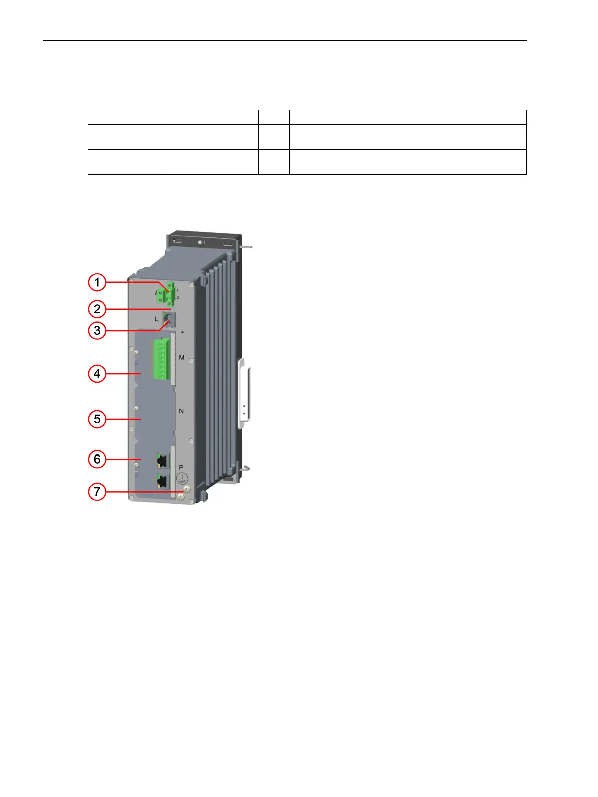
Power-Supply Module PS203 for the 2nd Device Row
Description
If you expand the device into the 2nd device row, you need the PS203 power-supply module.
NOTE
The PS203 power-supply module is always supplied with the expansion module and must always be
mounted at position 7.
Up to 5 additional expansion modules are possible in the 2nd device row. The scope of delivery of the PS203
power-supply module includes 1 connecting cable for the 2nd device row, 1 angle rail, 1 sealing panel and 1
adaptor bracket.
The PS203 power-supply module has no additional functionality. It is used exclusively to supply power to the
2nd device row.
The rated voltage variant of the PS203 power-supply module must always match the PS201 power-supply
module of the base module.
3.1.3
3.1.3.1
Electronic Modules
3.1 Power-Supply Modules of the Modular Devices
52 SIPROTEC 5, Hardware Description, Manual
C53000-G5040-C002-N, Edition 04.2022

 Loading...


