(1) Time synchronization G
(2) Plug-in module position E
(3) Terminal for detached on-site operation panel H
(4) Plug-in module position F
(5) Integrated Ethernet interface J
(6) Connection to expansion module with plug-in module assembly CB202
(7) Protective grounding terminals
[le_lmnppo, 2, --_--]
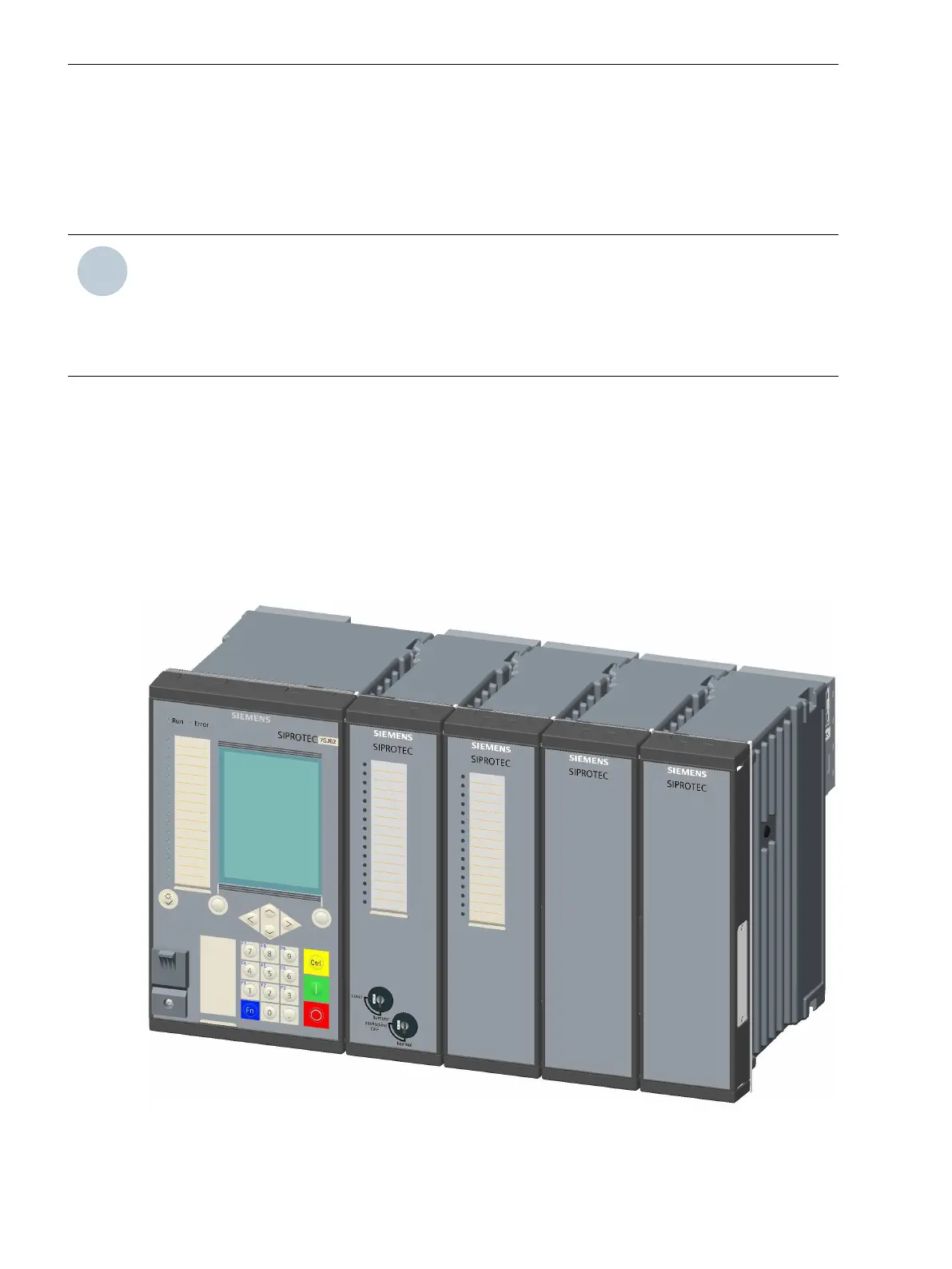
Figure 4-2
Plug-In Module Positions and Communication Terminals in the Expansion Module with CB202
(1) 2-pole terminal to connect power supply
(2) COM link L (connection to interface K of the base unit)
(3) Plug-in module position M
(4) Plug-in module position N
(5) Plug-in module position P
(6) Protective grounding terminals
NOTE
You cannot insert any communication module at plug-in module position M. The plug-in module posi-
tion M is intended for a measuring-transducer module only.
Plug-In Modules
4.2 Communication Modules
156 SIPROTEC 5, Hardware Description, Manual
C53000-G5040-C002-N, Edition 04.2022

 Loading...


