NOTE
You can only use the LPIT Module IO240 with the LPIT Connection Box (C53207-A9443-B1-4).
You must use the cable L45551-P42-B5 from the LEONI Special Cables GmbH.
The maximum allowed cable length is 100 m.
²
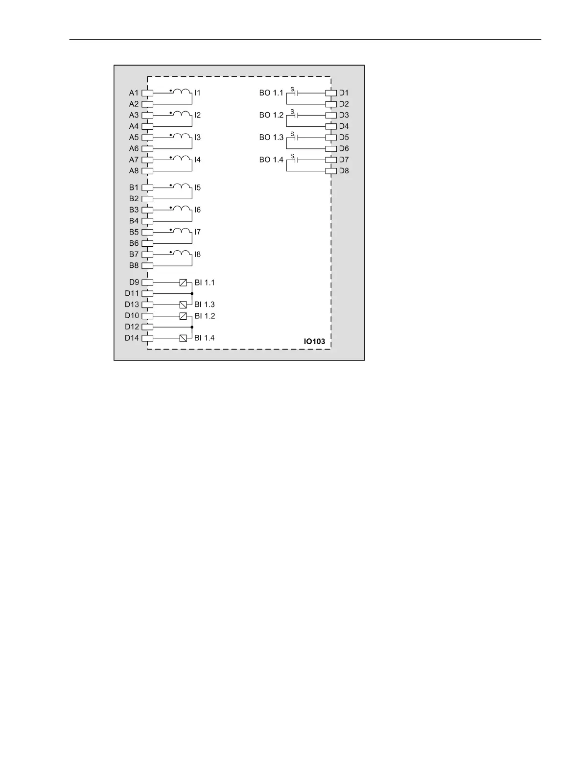
Connect the signal cables to the corresponding terminals, refer to Figure 3-69.
²
Connect the ring-type lugs of the shield terminals with M4 screws (torque = 1.6 Nm) to the marked
terminals (shield) at the rear plate of the LPIT module.
Electronic Modules
3.2 Input and Output Modules of the Modular Devices
SIPROTEC 5, Hardware Description, Manual 117
C53000-G5040-C002-N, Edition 04.2022

 Loading...


