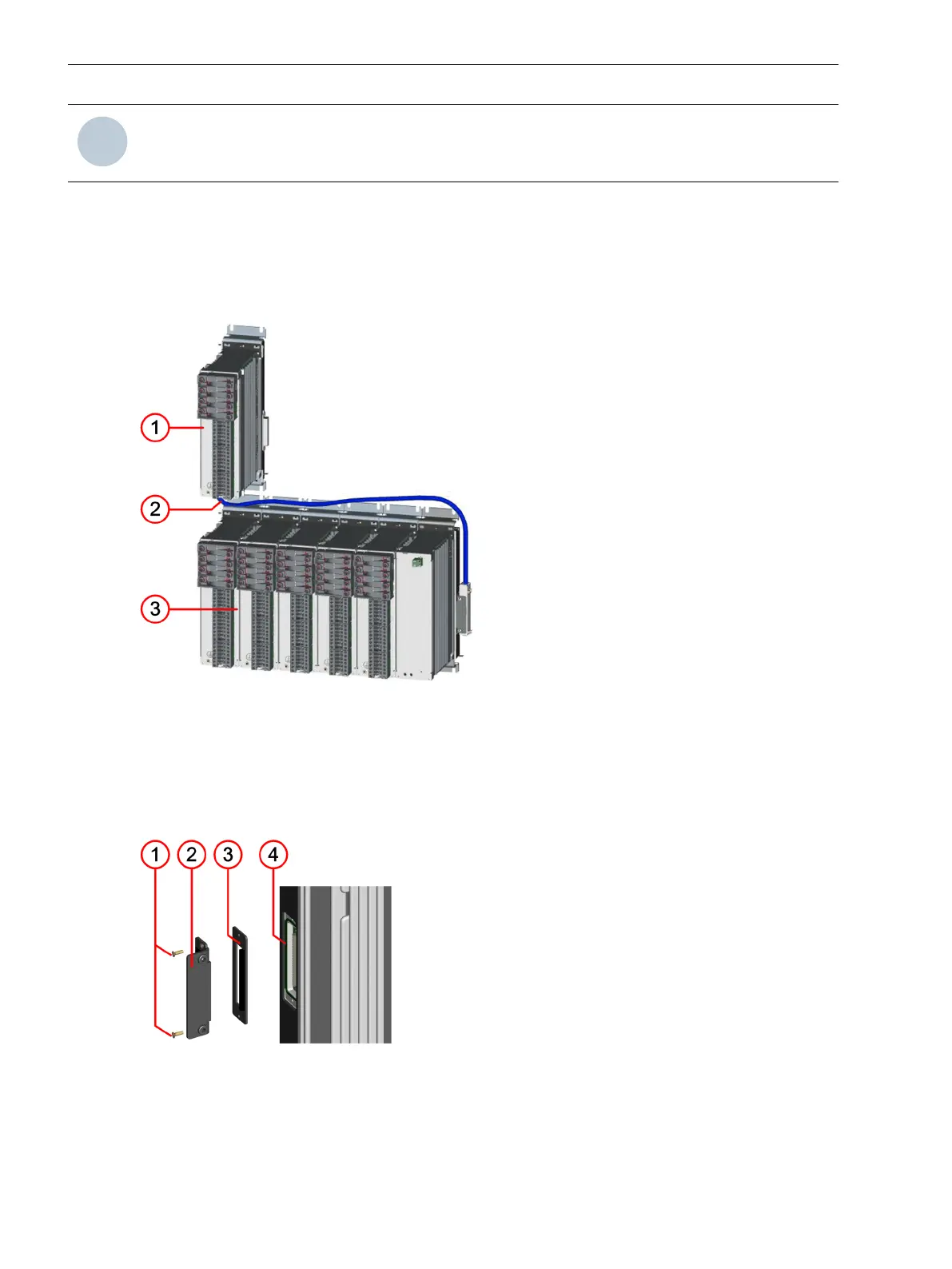
The preceding figure shows the use of both connections on one module for connecting the devices to 2 inde-
pendent masters following the same principle as with a single master.
Reorders
When reordering serial communication modules, specify the product code for the physical version of the
module. The order configurator (IPC configurator) shows you which applications are capable of running on the
module:
•
Serial
•
1-channel or 2-channel
•
Electrical or optical
USART-AB-1EL
Description Serial asynchronous communication module with one electrical inter-
face
Product code P1Z79
Figure
Connector type 2 x RJ45
Baud rate 1.2 kbit/s to 115.2 kbit/s
Protocol IEC 60870-5-103
DNP3
Modbus RTU
SUP serial
USART-AC-2EL
Description
Serial asynchronous communication module with 2 independent elec-
trical interfaces
Product code P1Z437
Figure
Connector type 4 x RJ45
4.2.3.2
4.2.3.3
Plug-In Modules
4.2 Communication Modules
164 SIPROTEC 5, Hardware Description, Manual
C53000-G5040-C002-N, Edition 04.2022

 Loading...


