Mounting and Commissioning
3.2 Checking Connections
SIPROTEC, 7SK80, Manual
E50417-G1140-C344-A4, Release date 08.2010
308
Connections at port B
When a serial interface of the device is connected to a control center, the data connection must be checked. A
visual check of the assignment of the transmit and receive channels is important. With RS232 and fiber optic
interfaces, each connection is dedicated to one transmission direction. For that reason the data output of one
device must be connected to the data input of the other device and vice versa.
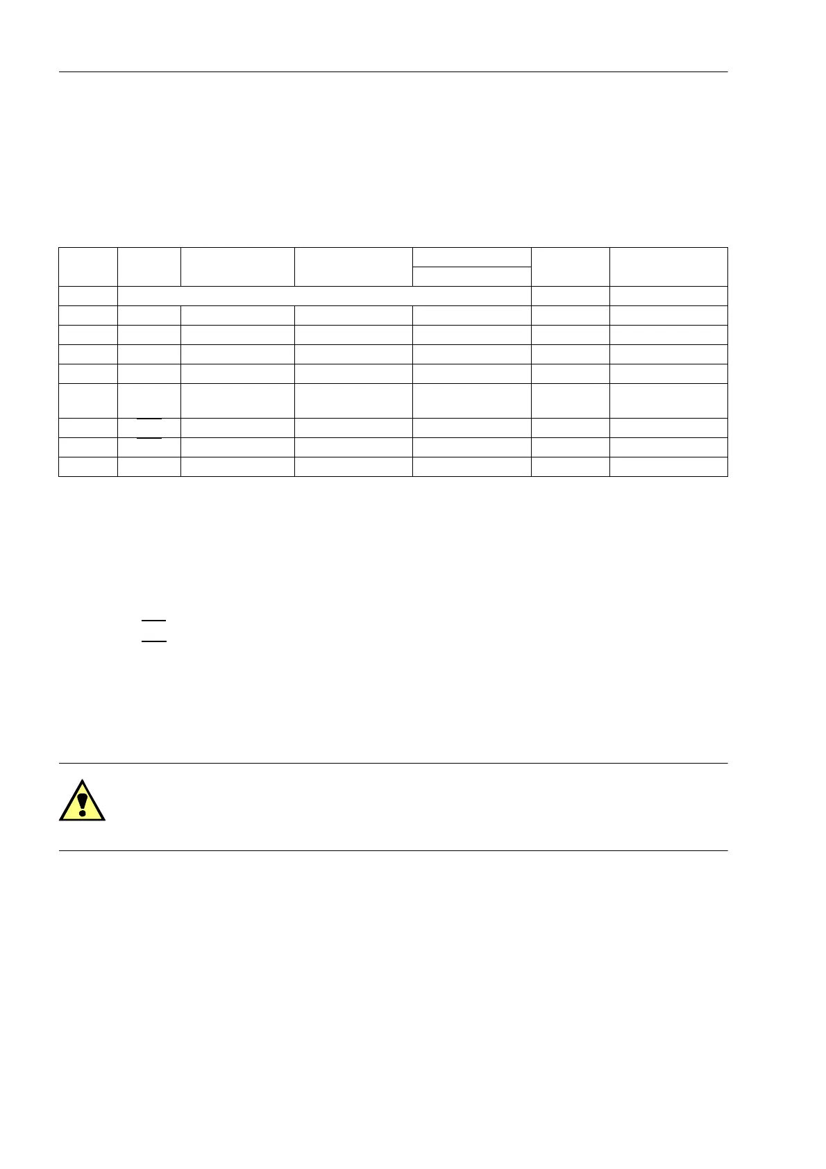
Table 3-4 Assignment of the port B sockets
1)
Pin 7 also carries the RTS signal with RS232 level when operated as RS485 interface. Pin 7 must therefore not be con-
nected!
With data cables, the connections are designated according to DIN 66020 and ISO 2110:
• TxD = Data output
• RxD = Data input
•RTS
= Request to send
•CTS
= Clear to send
• GND = Signal/Chassis Ground
The cable shield is to be grounded at both ends. For extremely EMC-prone environments, the GND may be
connected via a separate individually shielded wire pair to improve immunity to interference.
Fiber-optic Cables
WARNING!
Laser Radiation Class 1!
Do not look directly into the fiber-optic elements!
Signals transmitted via optical fibers are unaffected by interference. The fibers guarantee electrical isolation
between the connections. Transmit and receive connections are represented by symbols.
The standard setting of the character idle state for the optical fiber interface is „Light off“. If the character idle
state is to be changed, use the operating program DIGSI as described in the SIPROTEC 4 System Description.
Pin No. RS232 RS485 Profibus DP,
RS485
Modbus RS485 Ethernet
EN100
IEC 60870–5–103
redundant
DNP3.0 RS485
1 Shield (electrically connected with shield shroud) Tx+ B/B’ (RxD/TxD-P)
2 RxD – – – Tx– A/A’ (RxD/TxD-N)
3 TxD A/A’ (RxD/TxD-N) B/B’ (RxD/TxD-P) A Rx+ –
4 – – CNTR-A (TTL) RTS (TTL level) — –
5 GND C/C' (GND) C/C' (GND) GND1 — –
6 – – +5 V (max. load
<100 mA)
VCC1 Rx– –
7RTS
–
1)
––—–
8CTS
B/B’ (RxD/TxD-P) A/A’ (RxD/TxD-N) B — –
9 – – – – not available not available

 Loading...


