218/232
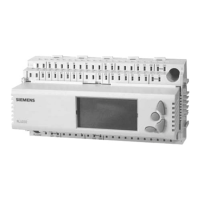
Building Technologies Boiler Sequence Controller RMK770 CE1P3132en
HVAC Products 16 Addendum 23.04.2009
16 Addendum
16.1 Configuration diagrams
Use of the configuration diagrams is explained in subsection 3.3.5 „Use of configuration
diagrams“
16.1.1 Terminal markings
The designations of the signal inputs and outputs and of the assigned connection
terminals are structured according to the following pattern:
Example Explanation
N.X3 N = controller RMK770
X3 = universal input
N.D1 N = controller RMK770
D1 = digital input
A9(2).Y1 A9 = type of extension module
(2) = 2nd
extension module of the same type
Y1 = analog output DC 0…10 V
N.Q7 N = controller RMK770
Q7 = relay output
16.1.2 Code letters
Physical inputs and outputs are marked with uppercase letters:
Code letter Explanation
N
Boiler sequence controller RMK770
A5 Universal module RMZ785
A7 Universal module RMZ787
A7 Universal module RMZ788
A9 Universal module RMZ789
D Digital input
X
Universal input
Q… Switching load (changeover or NO contact)
Y
Analog output DC 0…10 V
3P
3-position output in pairs
Internal signals are marked with lowercase code letters:
Code letter Explanation
x
Analog or digital
a Analog
d Digital
i Pulse
16.1.3 Configuration choices
A maximum of 3 extension modules with outputs for 7 single or twin pumps as well as
7 positioning outputs are available. The procedure for the configuration is always as
follows:
• from arrow to line
• from uppercase to uppercase letter
• from lowercase to lowercase letter
Use
Uppercase letters
Lowercase letters

 Loading...


