Model 4821/4820 Control/Communicator Installation Manual
3-10 150963
3.4 Access Control Operation
This section of the manual describes operation of access control features. An overview of
these operations is included in the Operations Summary in Section 5 of this manual.
3.4.1 Access Control Touchpad Menus
The
and
menus are for maintenance level access control operations.
The
menu is for controlling door lock/unlock schedules from the touchpad (see
Section 3.4.3 for more information). The
menu is for controlling users’ anti-
passback status (see Section 3.4.6). A brief summary of end-user operations are in section
3.4.2.
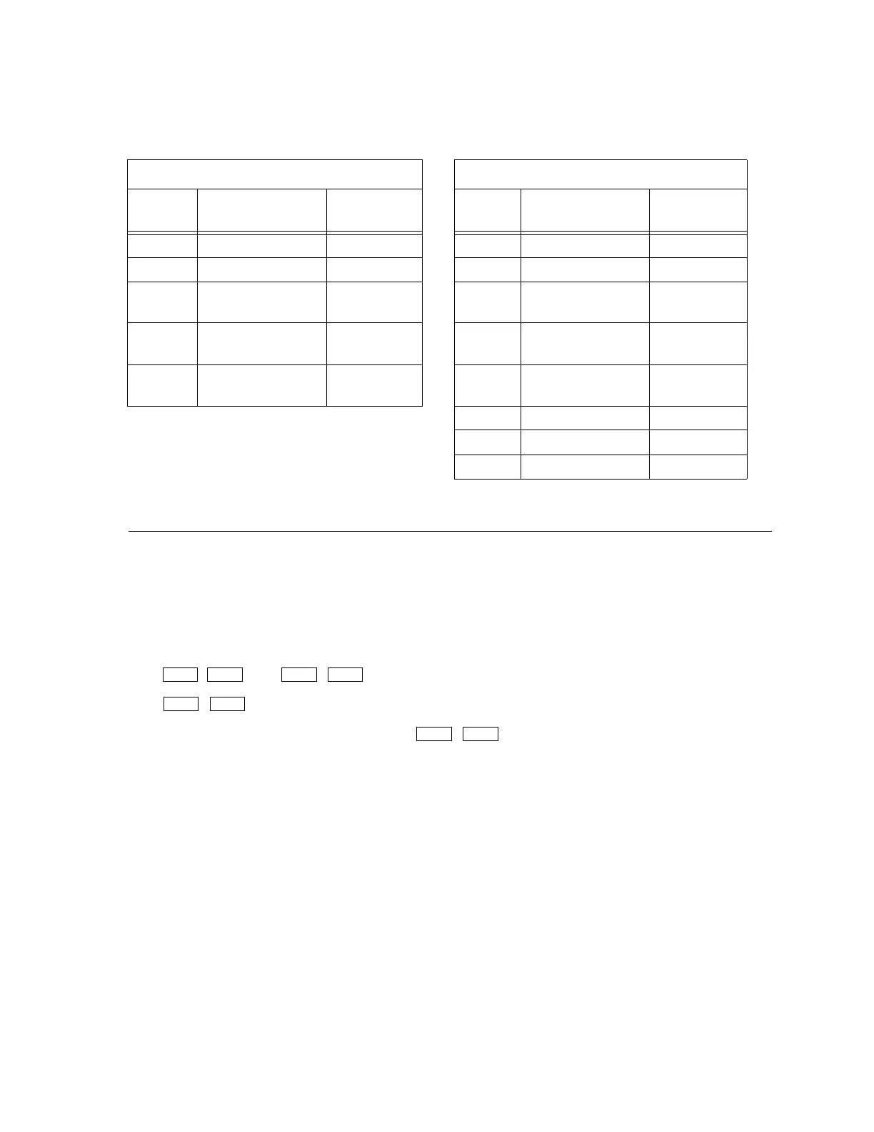
Table 3-2: Connector Descriptions
P2 (Card Reader) P4 (Door Access)
Pin
Number
Description
(P/N 130375)
Wire Color
Pin
Number
Description
(P/N 130378)
Wire Color
1 Circuit Ground Black 1 C+ is +12V Brown
2 LED Brown 2 Zone Input 1 Red
3 Data 0’s Green 3 Relay Contact
(Common)
Orange
4 Data 1’s White 4 Relay Contact
(Normally Open)
Ye ll ow
5 +5 VDC Red 5 Relay Contact
(Normally Closed)
Green
6 Not used Blue
7 Zone Input 2 Violet
8 C+ is +12V Gray
DOOR BYPS DOOR ENTR
DOOR BYPS
DOOR