Control Panel Description and Installation
150964 4-5
4.6 Power Switch
The power switch is disabled by the power switch bypass jumpers, to enable the power switch
cut both jumpers. Make sure the power switch is off when you are installing the system. See
Figure 4-1 for location of the power switch and power switch bypass jumpers.
Note: The power switch bypass jumpers can not be cut for UL 864 and NFPA (Chapter 4) fire installations. (See
Section 1.4.3.5.)
4.7 Mounting the Model 4821/4820 Panel
When selecting a location to mount the Model 4821/4820, consider the following:
• Panel must be accessible to main drop wiring runs.
• Panel must be located well within the secured area, but must be accessible for testing and
service.
• See environmental specifications described in Section 4.1.
If you are installing a UL Grade A Mercantile installation, all unused knockout holes must be
plugged using bolts and washers. (Model 7600 is a kit available from Silent Knight for this
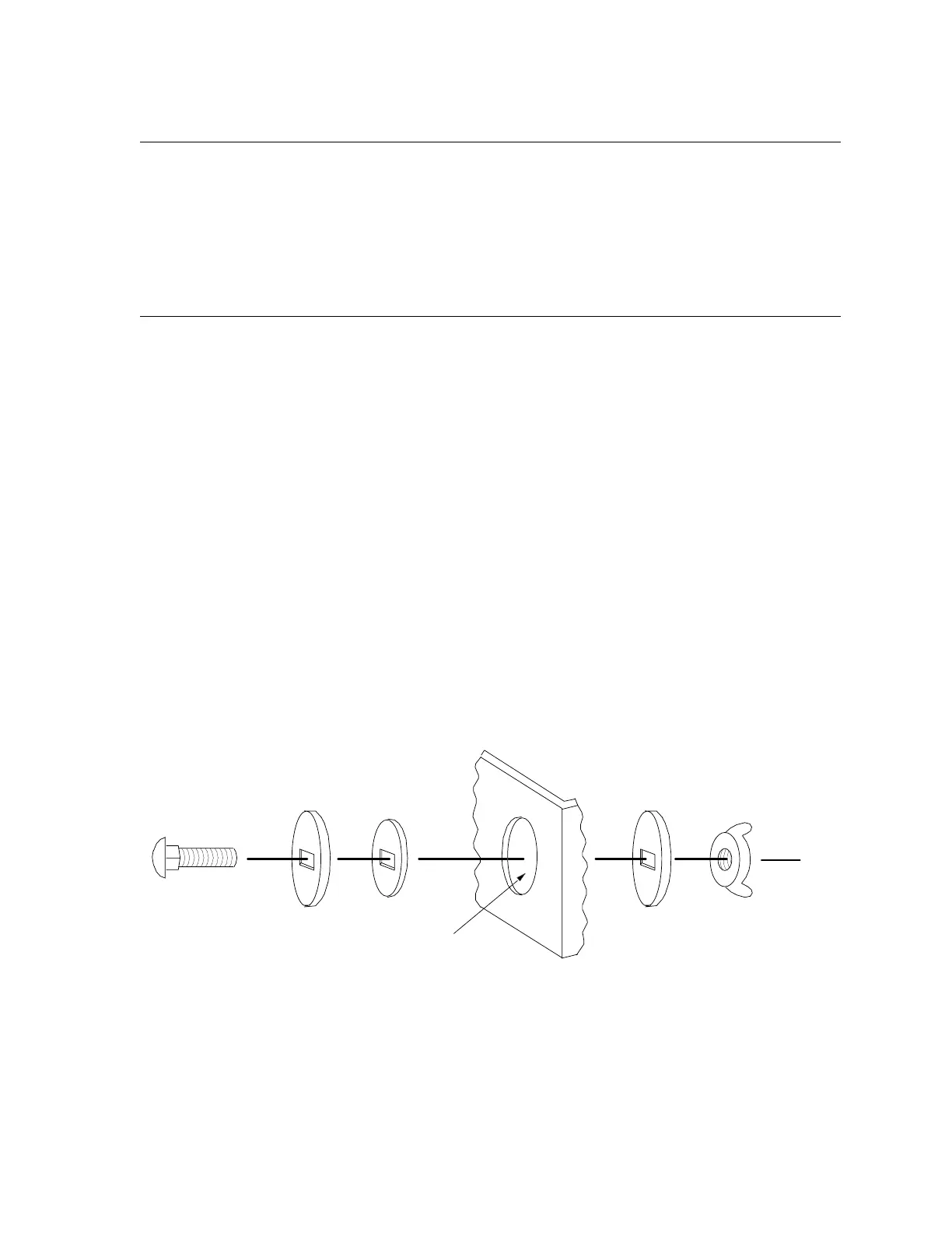
purpose. 6 sets per package.) Use the following steps to plug the knockout holes:
1. Remove all unused knockouts.
2. Install the carriage bolt and washers as shown in the diagram below. The smallest washer
should be placed
inside
the hole in the cabinet.
3. Firmly tighten the wing nut.
Figure 4-2 Knockout Plug Installation
CARRIAGE
BOLT
LARGE
WASHER
SMALL
WASHER
WING
NUT
KNOCKOUT HOLE
LARGE
WASHER
CABINET