EasyManuals Logo

Simplex 4100ES-S1 User Manual

Simplex 4100ES-S1
128 pages
To Next Page IconTo Next Page
To Previous Page IconTo Previous Page
Page #67 background imageLoading...
Page #67 background image
4-7
The Alarm Relay Card
The Alarm Relay Card mounts on, and is driven by, the SPS. It has 3 relays, each
providing one set of voltage-free contacts. It is fitted to the basic 4100ES-S1 as standard.
The relays are able to be configured under custom control, but the default operation is for
system status, i.e. Fault (Trouble), Isolate (Supervisory), and Alarm, respectively. These
are commonly used to drive the Brigade signalling device (ASE or PPU/AIU). See the
next section for more details about Brigade Devices.
TROUBLE SUPERVISORY ALARM
F3 F2 F1
p
3
p
2
p
1
LD1 LD2 LD3
Fault
(Trouble)
Isolate
(Supervisory)
Alarm
10 Way FRC
connects to P7
on SPS
Energised Relay LEDs
Normally Closed/
Normally Open
Jumpers
3A, 5 x 15mm Fuses
TB1 Terminal Block
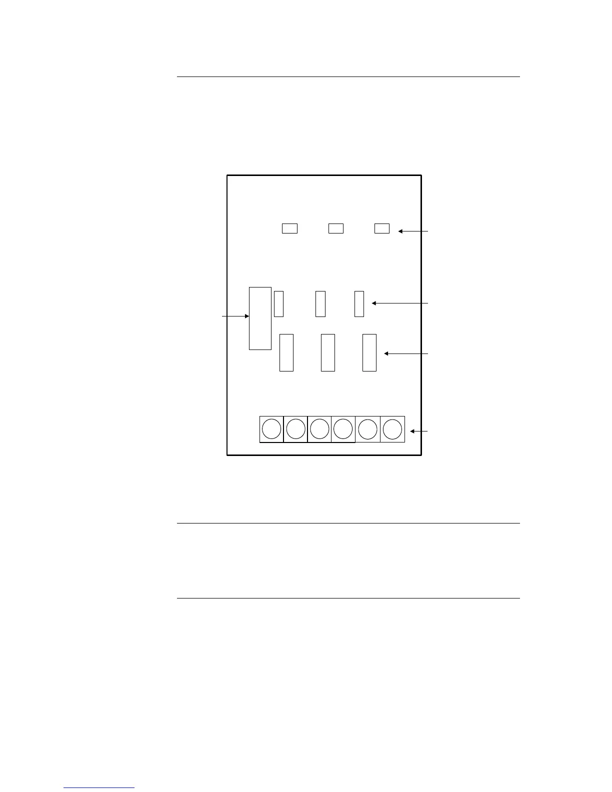
Figure 4-1. The Alarm Relay Card
The Alarm Relay Card mounts on the SPS adjacent to the largest relay K3. With the
power disconnected, fit the card using the three plastic stand-offs and one Torx screw
with plastic sleeve.
Connect P4 on the relay card to P7 on the SPS with the 10 way FRC provided.
Overview
Mounting
(factory installed)

Table of Contents

Other manuals for Simplex 4100ES-S1

Questions and Answers:

Question and Answer IconNeed help?

Do you have a question about the Simplex 4100ES-S1 and is the answer not in the manual?

Simplex 4100ES-S1 Specifications

General IconGeneral
BrandSimplex
Model4100ES-S1
CategoryControl Panel
LanguageEnglish

Related product manuals