Step 5. Installing Modules into Expansion Bays, Continued
Motherboards can be installed on top of the PDI in expansion bays. The data and
power that would normally be bussed via the PDI are routed across the motherboards
via their left and right connectors (J1 and P1).
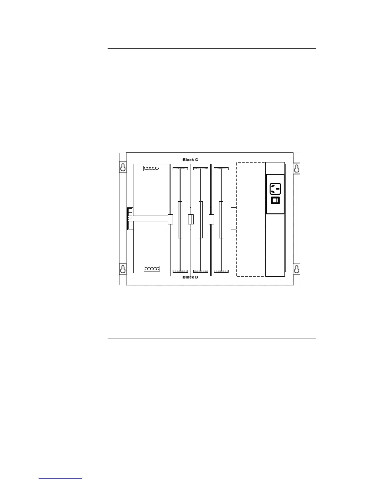
Up to four 2” (51 mm) x 11 ½” (292 mm) motherboards can be installed in an
expansion bay if the pins on the left connector (usually P1) on the leftmost
motherboard are removed. See Figure 2-8.
Motherboards should be added from left to right, starting in slot 3.
Relay motherboards must be the rightmost motherboards.
The CPU motherboard generates the 8V supply required for 4100A motherboards. It
also has the 4100A style Molex connectors to which a harness can be fitted as in
Figure 2-6.
Power Distribution Interface (PDI)
Block A Block E
Block B Block F
Slots 7 & 8
I/O Wiring
4" x 5" Module
Main Outlet (GPO)
Mounting Bracket
T-Gen 50 on mounting bracket (if fitted)
(heatsink intrudes into slot 6 space)
4100 Option
cards cannot be
fitted in these
slots because of
clashes with the
front panel
display
controllers
Up to four 2” x 11 ½” motherboards can be mounted in the
expansion bay. Three motherboards fit into Slots 3 through 5; the
fourth can be added in Slot 6 if a T-GEN 50 is not fitted.