Step 6. Installing LED/Switch Modules into Expansion Bays, Continued
If more than 32 zones are required, a second controller (4100-1289) will be required.
Note that an ME0456 fan control module counts as 8 zones when adding up the controller
requirements.
LED 1. This LED illuminates if communication loss between the controller and the CPU
occurs. It is independent of jumper P1 (which configures different communication loss
features).
The 64/64 LED/switch controller requires physical configuration, but the LED/Switch
modules do not. Switch controller configuration consists of setting jumper P1 and setting
the card address. See Figure 2-12. In the 4100ES-S1, the first display controller is
address 3 and the second has address 4. Card addressing is covered in Appendix A.
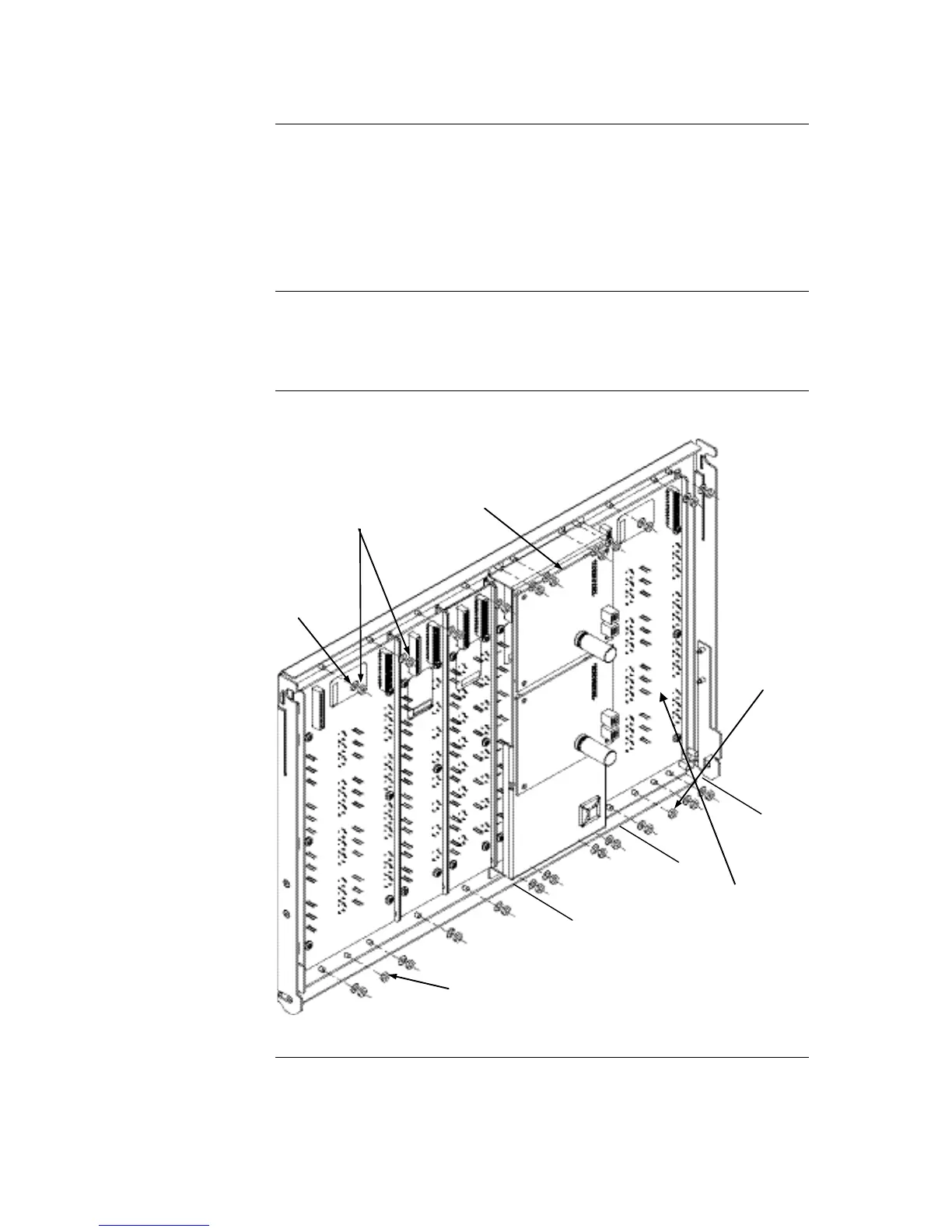
Refer to Figure 2-13 to mount the display cards to the front of the expansion bay.
Figure 2-13. LED/Switch Card Mounting
Continued on next page