4100ES Fan Control Module
The ME0456 is a 4100ES style Switch/LED display module designed specifically for fan
control. It complies with the requirements of AS 1668.1:1998. It has rotary switches and
LEDs for 4 sets of fans. In order to accommodate the required rotary switches, the front
plate is joggled forward so that it protrudes through the trim.
The Fan Control switch positions of ON, AUTO and OFF, are permanently marked on the
faceplate label, as required by AS 1668. The name area accommodates 3 rows of 6 letters
at 5mm.
The labelling of the LEDs, ON, FLT, and OFF is marked on the removable fan name
label card, LB0605, supplied with the module.
The card may be reversed and different LED labelling used, e.g. for damper controls.
A template version of this label is available as LB0605. This template allows entry of the
fan name on a PC for local printing. LED names may also be revised.
The Fan Control module mounts to the frame of the 4100ES-S1 Expansion bay door from
the front, in a similar fashion to display modules. Mounting nuts and washers are
provided.
Connection from “Out” of the adjacent Switch/LED module (or 64/64 Controller if it is
the first module on that Controller) to “In” on the module is by the flat flexible cable
provided (166-226).
The module is programmed as a standard 8 Switch/16 LED module. Up to four modules
can be driven by one 64/64 Switch/LED Controller.
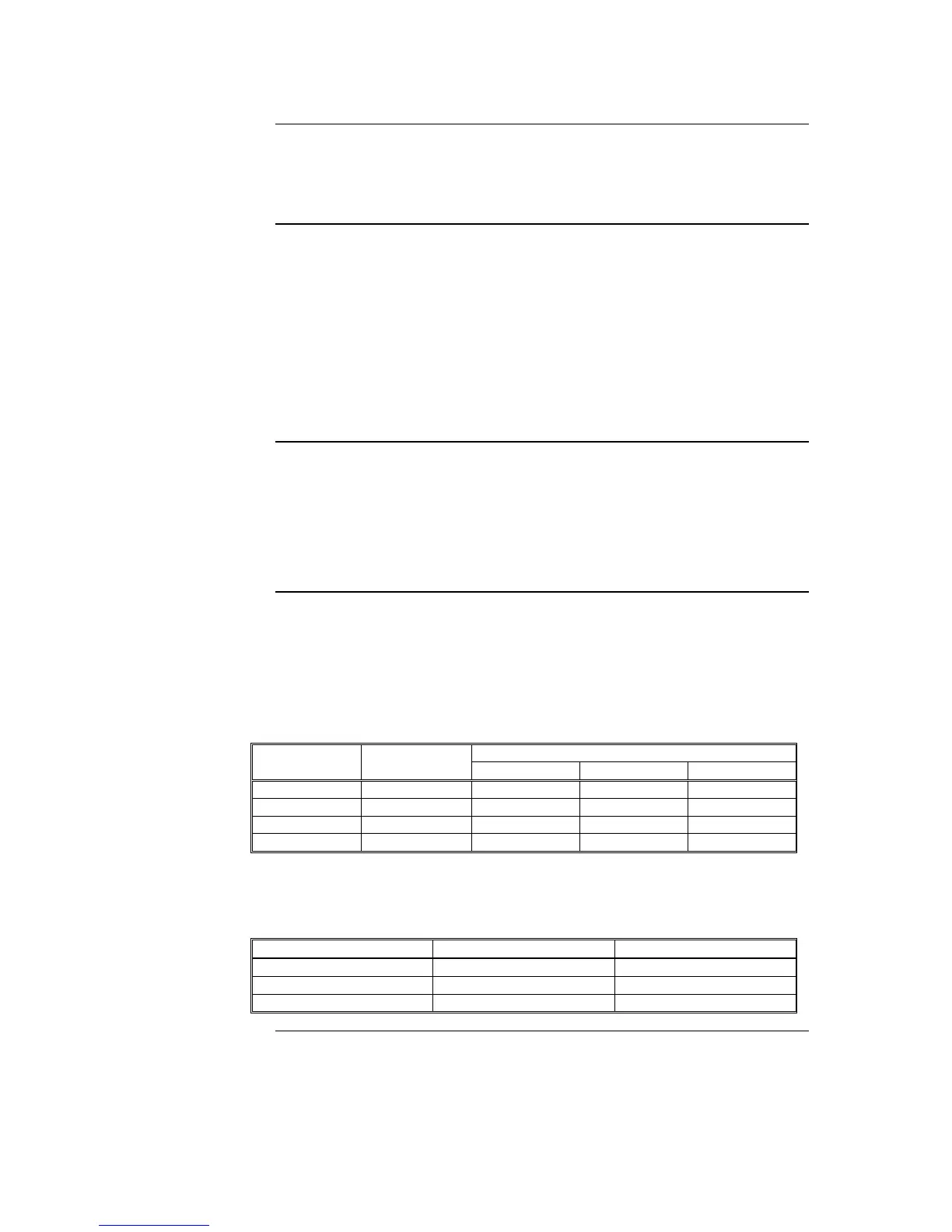
Each fan control with one rotary switch uses two of the 8 “switches”, and 3 of the 16
LEDs of an 8 Switch/16 LED module as per Table 2-2. The other 4 LEDs are not fitted so
must not be programmed, since it serves no purpose.
Table 2-2. Switch/LED Format