EasyManuals Logo

Simplex 4100ES-S1 User Manual

Simplex 4100ES-S1
128 pages
To Next Page IconTo Next Page
To Previous Page IconTo Previous Page
Page #27 background imageLoading...
Page #27 background image
2-7
Introduction to 4100ES-S1 Cabinet, Continued
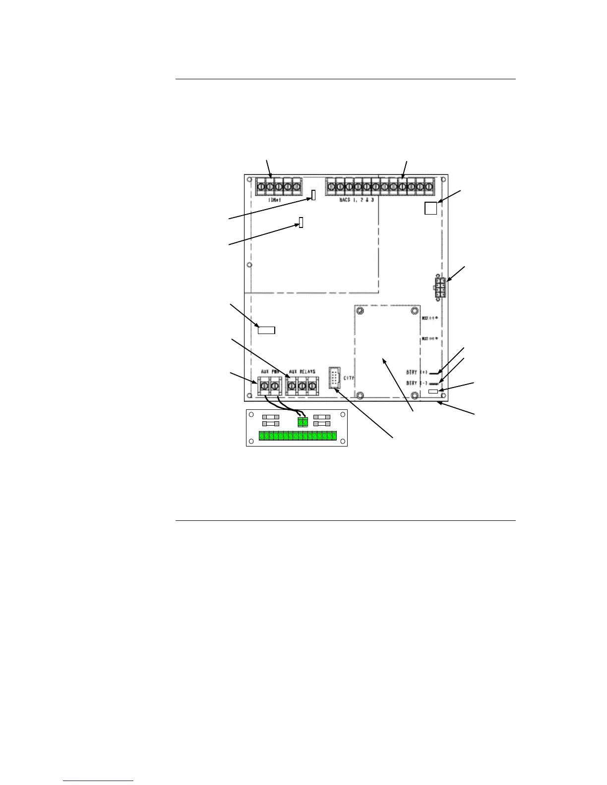
The basic 4100ES-S1 has a Fuse Distribution Board mounted on the SPS chassis and
connected to the Auxiliary Power terminals. See Figure 2-4. This provides four sets of
supply terminals, each individually fused at 1A, but the collective capacity is still limited
to 2A from the Auxiliary Power supply. The fuses are not directly supervised.
Figure 2-4. System Power Supply
Continued on next page
ALARM RELAY CARD
MOUNTING
AREA
ALARM RELAY
CARD
CONNECTOR
(P7)
AUXILIARY RELAY
TERMINAL BLOCK
(TB4)
AUXILIARY POWER
TERMINAL BLOCK
(TB3)
AC
CONNECTOR
(under board)
BATTERY
CONNECTORS:
P4
P5
POWER/COMM TO
CPU
MOTHERBOARD
(P8)
DEVICE ADDRESS
SWITCH (SW1)
IDNET SHIELD JUMPER
(P2)
CITY/RELAY CARD
TROUBLE INDICATION
JUMPER (P3)
EARTH
FAULT
MONITOR
JUMPER (P1)
NAC TERMINAL BLOCK (TB2)
IDNET TERMINAL BLOCK (TB1)
POWER/COMM TO
NEXT PDI (P6)
24 V IN
+
-
+
-
+
-
+
-
+
-
+
-
+
-
+
-
F4 F1F3 F2
FUSE DISTRIBUTION BOARD

Table of Contents

Other manuals for Simplex 4100ES-S1

Questions and Answers:

Question and Answer IconNeed help?

Do you have a question about the Simplex 4100ES-S1 and is the answer not in the manual?

Simplex 4100ES-S1 Specifications

General IconGeneral
BrandSimplex
Model4100ES-S1
CategoryControl Panel
LanguageEnglish

Related product manuals