EasyManuals Logo

Simplex 4100ES-S1 User Manual

Simplex 4100ES-S1
128 pages
To Next Page IconTo Next Page
To Previous Page IconTo Previous Page
Page #38 background imageLoading...
Page #38 background image
2-18
Step 6. Installing LED/Switch Modules into Expansion Bays, Continued
Figire 2-11shows an LED/switch bay from the user‟s perspective.
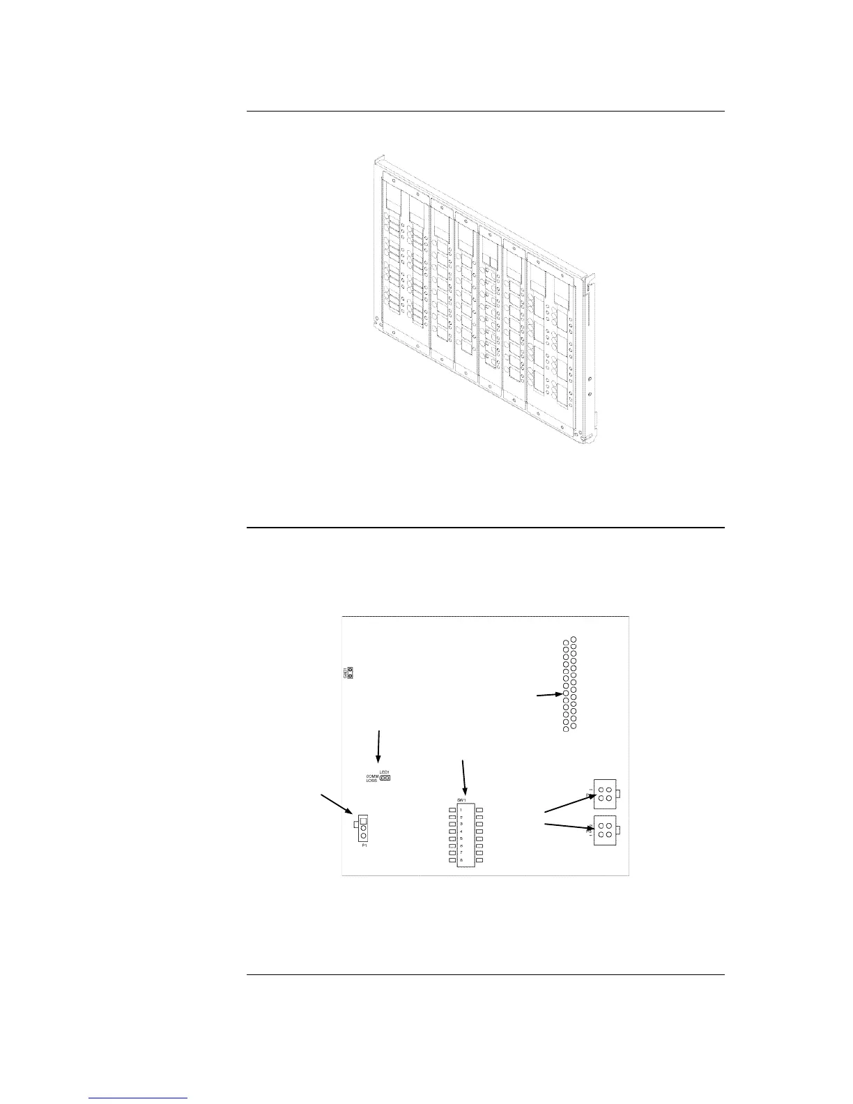
Figure 2-11. LED/Switch Modules
The LED/switch controller card is a 4100 slave that mounts behind two LED/switch
modules. Each LED/switch controller handles up to 64 switches and 64 LEDs on the
modules and communicates their status to the 4100ES CPU. This is sufficient for 32
zones.
Figure 2-12. LED/Switch Controller
The standard configuration of 4100ES-S1 uses 4100-1282 cards for zone displays, with
programming so that pressing any switch toggles the Isolate state of the corresponding
zone.
Continued on next page
The LED/Switch
User Interface
LED/Switch
Controller Card
LED/SWITCH DISPLAY
CONNECTOR
(P4; reverse side)
POWER/COMMS
CONNECTORS
(P2)
(P3)
COMM LOSS LED
(LED1)
ADDRESS DIP
SWITCH (SW1)
REMOTE ANNUNCIATOR
JUMPER (P1)

Table of Contents

Other manuals for Simplex 4100ES-S1

Questions and Answers:

Question and Answer IconNeed help?

Do you have a question about the Simplex 4100ES-S1 and is the answer not in the manual?

Simplex 4100ES-S1 Specifications

General IconGeneral
BrandSimplex
Model4100ES-S1
CategoryControl Panel
LanguageEnglish

Related product manuals