Step 5. Installing Modules into Expansion Bays, Continued
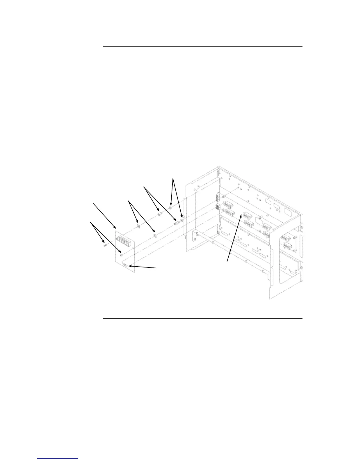
The power distribution interface (PDI) is mounted to the back of the expansion bay. See
Figure 2-9. The PDI contains slots for up to eight 4”x 5” slave cards. Since the PDI
carries power and data across the entire bay, it solves most interconnection issues,
especially between 4”x 5” cards.
Use the following instructions and the figure below to mount 4”x 5” slave cards to the
expansion cabinet.
1. Screw two standoffs and washers to the appropriate holes in the back of the
cabinet. These holes must line up with the screw holes in the 4”x 5” card. See
Figure 2-9.
2. Plug the 4”x 5” card into the appropriate blind mating connector. Seat the card
firmly onto the PDI when installing to ensure complete insertion of the power
connector into the PDI.
3. Secure the other end of the card to the standoffs with two 6/32” x ¼” torx screws
and washers.
Figure 2-9. Slave Card/PDI Connection
Continued on next page