SPS Auxiliary Power Wiring, Continued
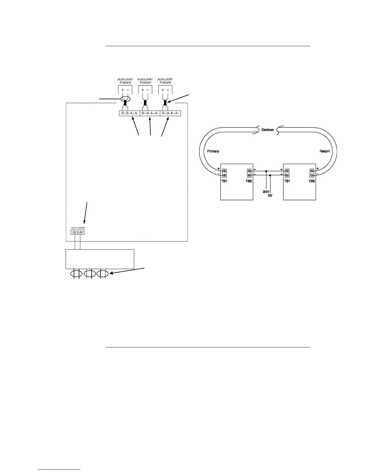
The SPS can connect to auxiliary power appliances via the dedicated auxiliary power tap
(TB3). See Figure 5-9. If more power is needed, any of the three NAC outputs can be
used for auxiliary power.
Figure 5-9. Auxiliary Power Wiring
Maximum load per NAC: 3A alarm, 2A non-alarm load
Maximum load per Fuse Distribution Board output: 1A, limited to 2A collectively.
Class A wiring is possible only if 4090-9117 Power Isolators are used.
Ferrite beads must be fitted on NAC wiring. Use kit 4100-5129 (3 beads).
Class A Aux power wiring requires the use
of 4090-9117 IDNet Power Isolators, as
shown above.
Dedicated auxiliary
power screw terminal
(configured in the
Programmer)
NAC points must be
reconfigured as
auxiliary power
output points in the
programmer
Ferrite bead
required for EMC
compliance. Use
SX0005 or kit
4100-5129.