Step 6. Installing LED/Switch Modules into Expansion Bays, Continued
All types of modules are mounted to the front of a bay, and are connected to each other
via a ribbon cable. Each module operates by the same rules: when a button is pressed, the
controller card sends the CPU the information, and the action programmed for that button
occurs.
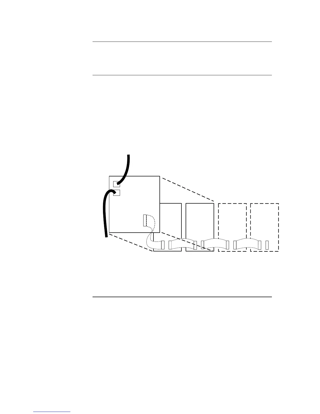
To interconnect display cards and connect the controller card to a power source:
1. Use harness 734-008 to connect P2 on the controller card to one of the 4-pin
connectors on the PDI. See Figure 2-15.
2. If there are two controller cards, use harness 734-036 to connect P3 on the first
controller card to P2 on the second controller card. The order does not matter.
Connect P4 of the controller to P1 of the left-most display module, with the ribbon cable
provided (the first two display modules are fitted in the factory). Connect P2 of this
display module to P1 of the next module, up to a maximum of four modules. Repeat for
the second controller, if fitted.