60
SC213 Diesel Engines
4. Fit the outer C.I. ring over the coil spring. Ensure coil
spring gets seated properly inside the ring groove
and the coil spring latch is on the opposite side
of the ring open end gap.
5. Using piston ring expander, install the No.2 ring (Cast
Iron, Taper land with ‘Top’ marked).
6. Install the Top ring (Chromium inlaid with ‘Top’
marked).
7. Place each piston ring end gap as far apart from
neighboring gaps as possible. Ensure that gaps are
not positioned in the thrust and pin direction.
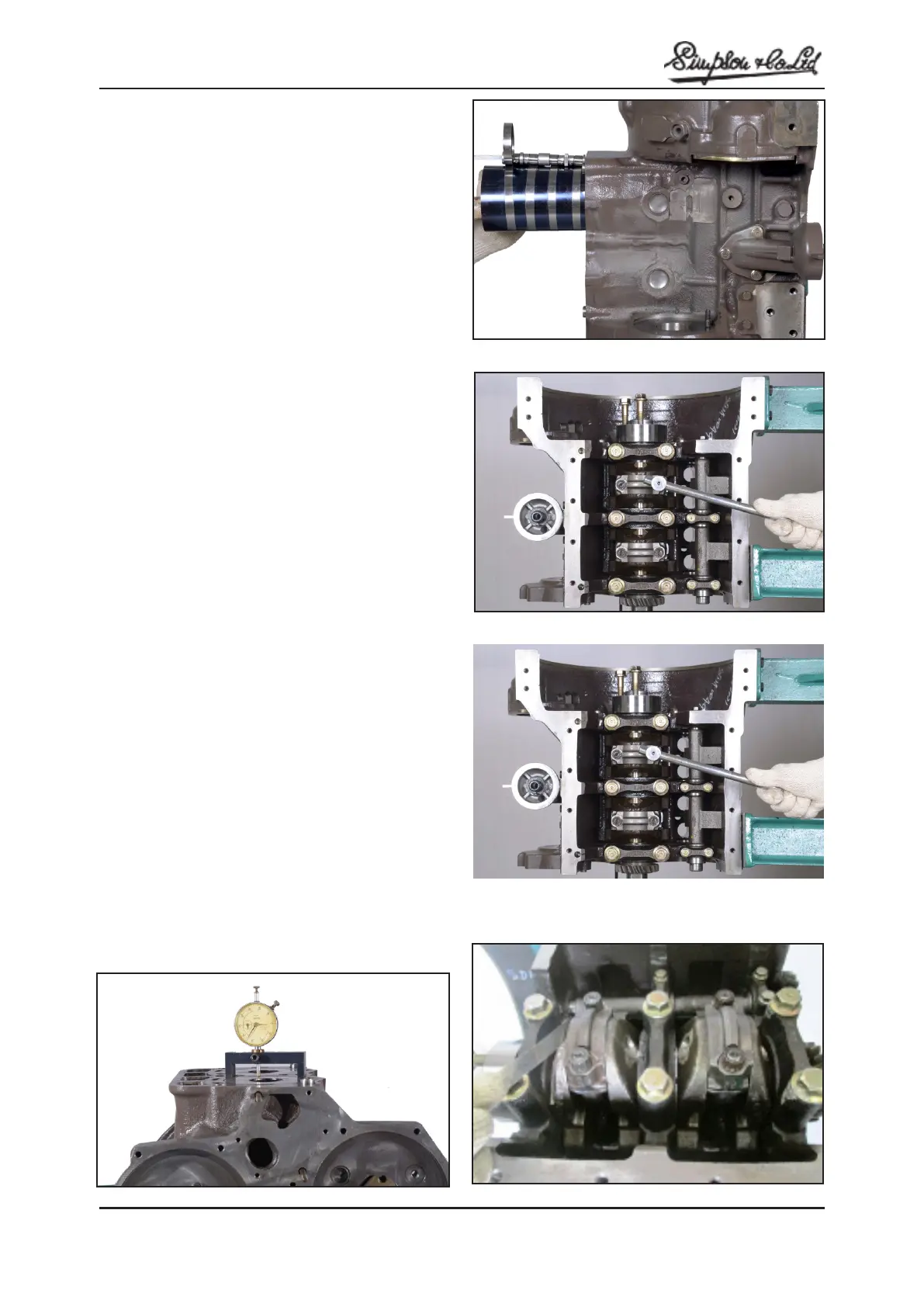
8. Hold the piston rings firmly with piston ring
compressor as they are inserted into cylinder.
9. Make sure that the arrow mark on the piston
crown is towards the front of the engine. (Offset of
combustion bowl in the crown toward fuel injection
pump side).
10. When connecting rod is installed, ensure that the
cylinder numbers put on the rod and caps assembly
match.
11. Tighten the rod cap nuts. Tightening torque to 65
Nm (48 lbf.ft)(Fig.M.15)
12. Rotate crankshaft by hand and note that all parts
move freely.
13. Check the piston height in relation to the top face
( ) of the cylinder as described below.(Fig.M.16)
When the crankpin is at top dead centre the crown
of the piston height in relation to cylinder block top face
must be with the limit. 0.05 mm (0.002’’) below or 0.35 mm
(0.014 in.) above block surface.
14. Check the big end side clearance on crankpin.
Side clearance: 0.3 / 0.5 mm (0.012/ 0.020 in.)
Note: Connecting rod and cap are numbered. While
assembling to engine, number side of connecting
rod should be on camshaft side.
Fig: M.13
Fig: M.14
Fig: M.15
Fig: M.16
Fig: M.17