61
SC213 Diesel Engines
CRANKSHAFT ASSEMBLY
The crankshaft runs in three pre-finished re-placeable
shell bearings lined with aluminium tin.
The seal at the rear end of the crankshaft is a Lip type
seal fitted in a one-piece housing.
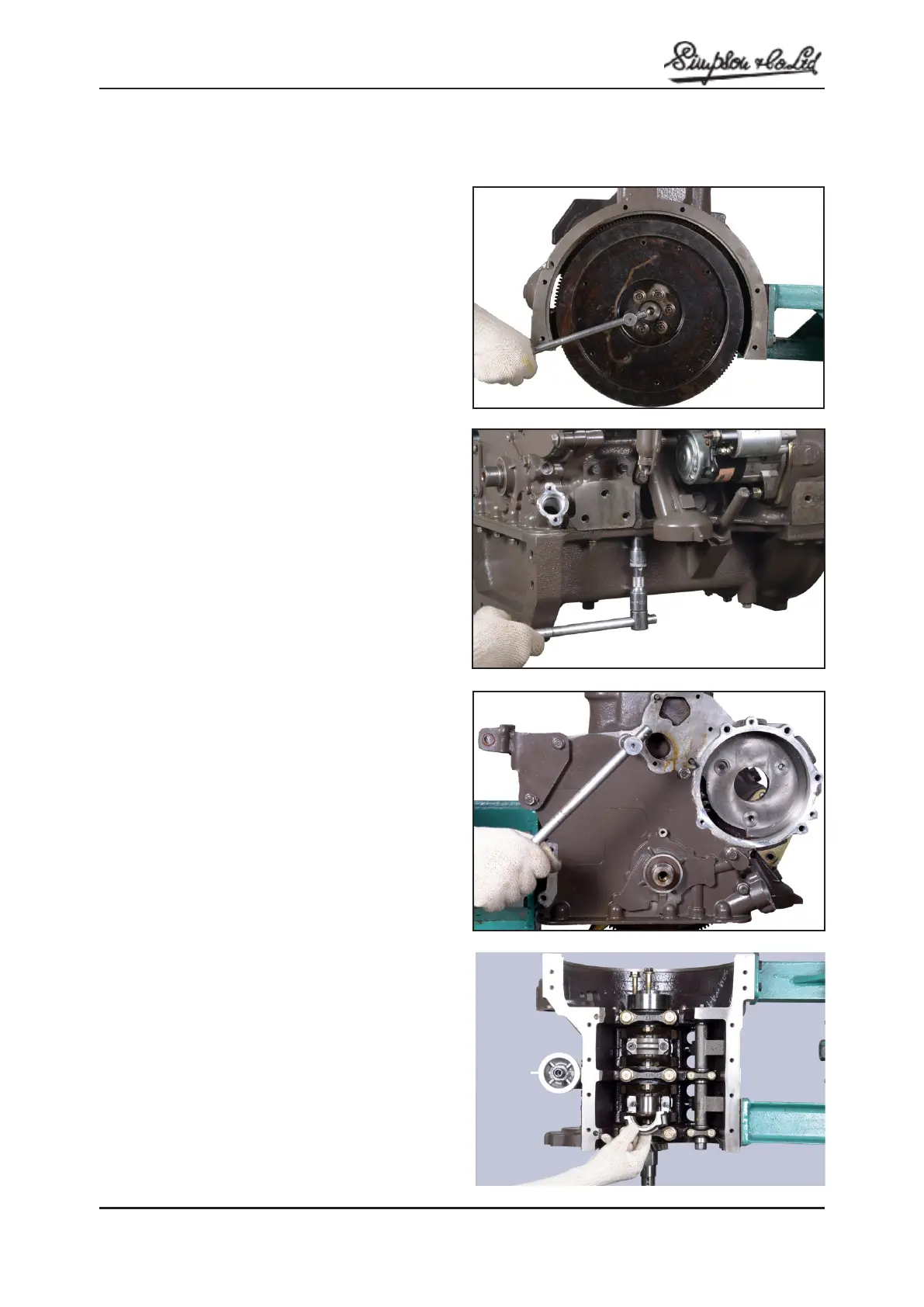
REMOVAL
1. Remove the fan belt, tensioner assembly and
crankshaft pulley.
2. Remove the startor motor.
3. Remove the flywheel, rear end oil seal housing and
oil seal.
4. Remove the cylinder head assembly.
5. Remove the sump.
6. Remove the timing case front cover.
7. Remove the connecting rod and piston assembly.
8. Remove setscrews and remove main bearing caps
and half bearings.
Note: Marks provided on connecting rod cap and main
bearing caps in order, according to the cap number.
9. Lift out the crankshaft.
INSPECTION
Check the crankshaft journals and pins for damage, uneven
wear and cracks.
Check the oil holes for restriction.Inspect the crankshaft
journals and pins for taper and out-of-round.
Crankshaft journal outer diameter: Standard
57.98 / 58.00 mm (2.282 / 2.283 in.)
Crankpin outer diameter: Standard
47.98/ 48.00 mm ( 1.889 / 1.890 in.)
Main Bearing and Connecting Rod Bearing
Visually inspect bearing for pealing, melting, seizure and
improper contact, replace if defective.
Note: It is important that the RADII on the main journals
and crankpins are maintained. If these are neglected, a
fatigue fracture is liable to occur. The main journal and
crankpin diameters should be checked to ascertain the
next appropriate under size to which the crankshaft can
be-reground,
Fig: N.1
Fig: N.2
Fig: N.3
Fig: N.4
Section N
CRANKSHAFT ASSEMBLY