52
SC213 Diesel Engines
CYLINDER HEAD
DISMANTLING
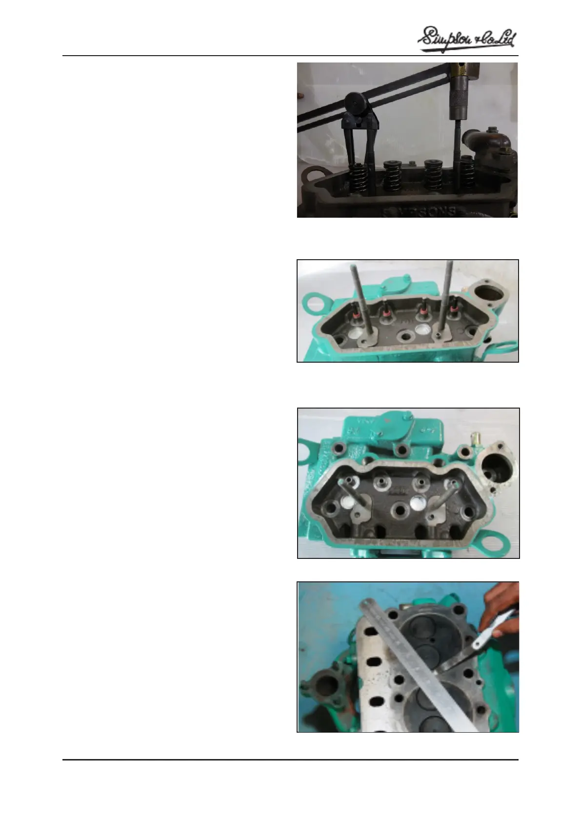
To Remove Valves
1. Remove cylinder head.
2. Remove the valves by depressing the spring cap
and spring by means of a valve spring compressor.
3. Remove the two half conical cotters. Remove the
spring caps, springs and washers. Take out the
valves.
Note: The valves should be suitably marked to ensure
it is fitted in to respective ports / cylinder.
4. Remove the valve stem seals with pliers.
Note: Do not reuse the valve stem seals.
INSPECTION
1. Check the cylinder head for cracks, damage and
coolant leakage. If cracked, replace the cylinder
head.
2. Remove scale, sealing compound and carbon
deposits completely. After cleaning the oil passages,
blow with compressed air to clear the passages.
3. Check the cylinder head surface for flatness in
transverse and longitudinal. If flatness exceeds the
limit in any direction, either replace the cylinder
head or machine head surface.(Fig.K.28 )
Cylinder head bow limit transverse and longitudinal:
0.03 / 0.05 mm (0.0011 / 0.0019 in.)
Valves and Valve Seats
1. The valves and valve seats should be reconditioned,
using grinding compound or valve seat cutting tool
as shown.
2. The valve seat angle is 45° for inlet valve and 45°
for exhaust valve.
3. Maximum height between the valve head and the
cylinder head bottom face should not exceed 0.15
mm (0.006’’) for both the inlet and exhaust valve.
Check by means of a suitable gauge.
Valves Inlet and Exhaust
The inlet valve stem dia.:
6.95 / 6.97 mm (0.273 / 0.274’’)
The Exhaust valve stem dia.:
6.93 / 6.95 mm ( 0.272 / 0.273’’)
Checking the cylinder head surface for flatness
Fig: K.25
Fig: K.26
Fig: K.27
Fig: K.28